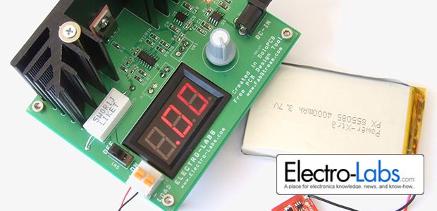
In this project, we are building a useful board which should take place on your bench. It is an adjustable electrical load which can sink up to 5A @ 30W continuously. This board will come to aid when you need to draw an exact amount of current from a supply. For instance to learn the current rating of a power supply, measure the heat dissipated on a circuit element, discharge a battery etc.
The electrical load lets you monitor the current by using the ampermeter on it. A multiturn variable resistor is used to set the current precisely. The circuit is powered by a 15V-18V power adapter. A large heatsink on the board helps dissipating the heat generated on the MOSFET which is the main component used for limiting the current.
Circuit Design
The circuit is drawn in SoloCapture the schematic editor of SoloPCB tools. SoloCapture makes the schematic drawing process very easy and fast. You can download SoloPCB tools at Fabstream.com for FREE.
You can download the SoloPCB design files of the project by using the link below.
The electrical load has a simple theory of operation. It is based on the voltage equality of the inverting and the non-inverting inputs of an opamp. We set the voltage applied to the non-inverting input by adjusting the resistor VR1. It varies between 0-0.5V. The supply of the voltage divider is the 2.5V precise voltage generated by the AD780 voltage reference IC. The voltage value on the inverting input must be also seen on the non-inverting input of the op-amp, LM324. So the voltage on the R5 resistor directly depends on the voltage we set. Setting the voltage on the R5 resistor means setting the current passing through it. This current is also the current drawn from the power supply under test. Output of the LM324 opamp works to realize the principle of the voltage equality of the inputs. So it drives the Q1 MOSFET gate in the linear region. The drain-source resistance (Rds) depends on the gate voltage. The output of the opamp sets the Rds to a proper level which limits the current on this path. Namely the MOSFET works as a resistive element which limits the current by the help of the opamp.
Since the MOSFET works as a resistive element, it dissipates heat depending on the current flowing through it. The simple equation P = VI gives us the amount of heat which will be generated on the MOSFET. To extend the power range of the load, we need to attach a heatsink to the MOSFET case.
The heatsink we used has a thermal resistance of 2.5 °C/W. The junction to case thermal resistance of the MOSFET is 0.75 °C/W. And finally we can assume the case to heatsink thermal resistance as 1.75 °C/W. The total thermal resistance becomes 5 °C/W. Assume we will use the load in room temperature, namely 25°C. The IRF3710 MOSFET die can operate up to 175 °C so we can heat the MOSFET die up to 175 °C in ideal case. The temperature difference can be at most 175°C-25°C = 150°C. By using this value, we can calculate the maximum power that we can be dissipated on the electrical load. P = 150 / 5 = 30W.
IRF3710 MOSFET has a maximum drain to source voltage (Vds) rating of 100V. So you should not connect a power supply giving more than 100V.
30W, 5A and 100V are the limiting parameters of the load. So while connecting a supply to the load, you should calculate the power dissipation carefully. For example, if you connect a 30V power supply to the load, you should not exceed 1A in continuous mode. Otherwise the MOSFET will be damaged or permanently fail as soon as the MOSFET die temperature exceeds 175 °C.
One another parameter that should be considered while working with MOSFETs is the Safe Operating Ares (SOA) of the MOSFET. Since the current won’t exceed 5A and the power will be less than 30W, the MOSFET will always stay in the safe operating area. Anyway if you don’t obey the 30W rule, the MOSFET will blow immediately at high voltages.
For more detail: WIN an Arduino Uno R3 Development Board – Like to Win!

