Moving on from the last chapter where we explained an 8-bit ADC, in this instalment we have the Texas Instruments ADS1110 – an incredibly tiny but useful 16-bit analogue-to-digital converter IC. It can operate between 2.7 and 5.5 V so it’s also fine for Arduino Due and other lower-voltage development boards.
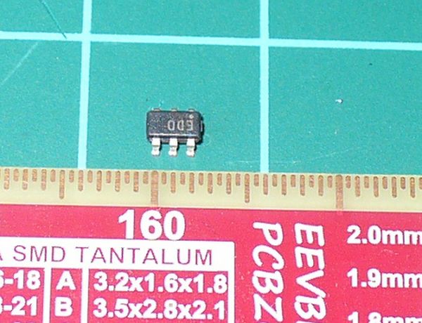
This is a quick guide to get you going with the ADS1110 ready for further applications. Before continuing any further, please download the data sheet (pdf) as it will be useful and referred to during this tutorial. The ADS1110 gives you the option of a more accurate ADC than offered by the Arduino’s 10-bit ADCs – and it’s relatively easy to use. The only block for some is the package type – it’s only available in SOT23-6:
The ADS1110 uses the I2C bus for communication, so if this is new to you – please review the I2C tutorials before continuing. And as there’s only six pins you can’t set the bus address – instead, you can select from six variants of the ADS1110 – each with their own address (see page two of the data sheet). As you can see the in the photo above, ours is marked “EDO” which matches to the bus address 1001000 or 0x48h. And with the example circuits we’ve used 10kΩ pull-up resistors on the I2C bus. You can use the ADS1110 as either a single-ended or differential ADC – But first we need to examine the configuration register which is used to control various attributes, and the data register.
Configuration register
Turn to page eleven of the data sheet. The configuration register is one byte in size, and as the ADS1110 resets on a power-cycle – you need to reset the register if your needs are different to the defaults. The data sheet spells it out quite neatly… bits 0 and 1 determine the gain setting for the PGA (programmable gain amplifier). If you’re just measuring voltages or experimenting, leave these as zero for a gain of 1V/V. Next, the data rate for the ADS1110 is controlled with bits 2 and 3. If you have continuous sampling turned on, this determines the number of samples per second taken by the ADC.
For more detail: Tutorial- Arduino and the TI ADS1110 16-bit ADC