I run a NFS/NIS network under a combination of OS’s for the upper-division physics lab here at CSUC, and one source of irritation is when one machine goes down and nobody lets me know until suddenly that machine is absolutely necessary NOW! So I figured an Arduino, living in the machine on my desk, might serve as an early-warning system for network problems.
I used red/green common-cathode LEDs for my indicators: that way the Arduino can set them to be green if the machine is fine, red if the Arduino notices a problem, and both (yellow-orange) if the computer status is “iffy” or “unable to determine due to other problems.”
With 13 computers I wanted to track and effectively 2 LEDs for each, that gave me a bit of a problem with the number of outputs on the Arduino. Here’s how I took care of it:
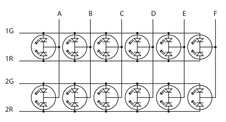
The Arduino cycles through the “bank select” outputs (1G-2R), sending each one high for 2ms in turn. While each bank is high, the “LED select” outputs (A-F) go LOW to turn on whichever LEDs I want on in that bank. Persistence of vision makes it look as if everything is on when it’s supposed to be, although each one is actually on for only 25% of the time.
Example, just for clarity: if you want the third LED from the left in the top row to be green, then when bank select 1G is high, make C low; and when bank select 1R is high, make C high also.
I used the “Ports” on the Arduino to quickly and efficiently turn the pins to the correct values all at once. Port D is pins 0-7, and port B is pins 8-13. Port B (six outputs) runs the LED Select pins (A-F), but port D is a bit less direct since I also want to use the serial port (pins 0-1) for communication with the host machine. So… Pins 2-5 of port D are the “bank select” pins, and I did not change anything on pins 0-1 so as to leave the serial port alone. Pins 6 & 7 were still unused, so since I still had one bicolor LED to drive I just put that on those last two pins.
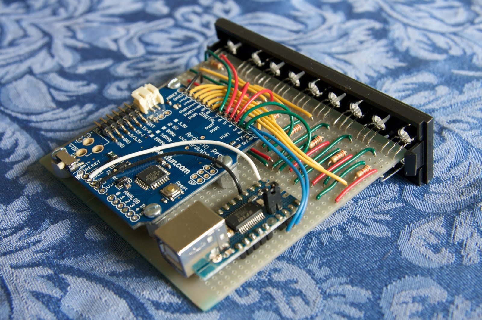
That’s the idea: here’s the hardware:
I used an Arduino Pro because (a) it was sitting around and (b) Sparkfun had shipped me a defective one in which two of the analog ports were solder-bridged together at the µcontroller. (Watch the quality control there, guys!) This particular application doesn’t use the analog inputs anyway, so I didn’t mind hardwiring the defective board into an assembly that wasn’t affected by the defect. I used a spare mini-USB adaptor for communications with the host computer: it was either that or dedicate my one remaining USB-Serial FTDI cable to the innards of the host. The front panel (black, to the upper right in the picture) is just a removable bay panel from the front of the host machine.
The software requires two separate programs: one to run on the host machine and determine the status of the various machines on my network, one to run on the Arduino and control the lights based on the information it gets from the host.
Here’s the host program, in Python; and here’s the Arduino program.
It works quite nicely! The host program runs as a cron-job once every minute, and the Arduino program sets the lights. If the Arduino doesn’t hear from the host for more than 90 seconds, it assumes the host is down and lights things accordingly.
For more detail: Network-status indicator Using Arduino