Summary of How to Interface GSM Module and Arduino-Send and Receive SMS
This article explains how to interface a SIM900-based GSM module with an Arduino Uno to send and receive SMS. It details the GSM module’s features, power requirements, and frequency compatibility. The tutorial describes two methods for connecting the GSM module to Arduino: directly using Arduino’s Rx and Tx pins or using SoftwareSerial library on other digital pins (e.g., pins 9 and 10) to avoid programming conflicts. The article also covers SIM card insertion, powering the module, detecting network connection via LED, and wiring connections for serial communication.
Parts used in the GSM Module to Arduino Interface Project:
- SIM900 GSM Module
- Arduino Uno
- SIM Card
- 12V, 1A DC Power Supply (for GSM module)
- Connecting wires (for serial Rx and Tx connections)
- Computer with Arduino IDE (for programming)
In this article, we are going to see how to interface GSM Module to Arduino. There are different kinds of GSM modules available in market. We are using the most popular module based on Simcom SIM900 and Arduino Uno for this tutorial. Interfacing a GSM module to Arduino is pretty simple. You only need to make 3 connections between the gsm module and arduino. So lets get to business!
A GSM Module is basically a GSM Modem (like SIM 900) connected to a PCB with different types of output taken from the board – say TTL Output (for Arduino, 8051 and other microcontrollers) and RS232 Output to interface directly with a PC (personal computer). The board will also have pins or provisions to attach mic and speaker, to take out +5V or other values of power and ground connections. These type of provisions vary with different modules.
Lots of varieties of GSM modem and GSM Modules are available in the market to choose from. For our project of connecting a gsm modem or module to arduino and hence send and receive sms using arduino – its always good to choose an arduino compatible GSM Module – that is a GSM module with TTL Output provisions.
Notes on GSM Module
1. We use SIM900 GSM Module – This means the module supports communication in 900MHz band. We are from India and most of the mobile network providers in this country operate in the 900Mhz band. If you are from another country, you have to check the mobile network band in your area. A majority of United States mobile networks operate in 850Mhz band (the band is either 850Mhz or 1900Mhz). Canada operates primarily on 1900 Mhz band. Please read this wiki entry on GSM Frequency Bands around the World.
2. Check the power requirements of GSM module – GSM modules are manufactured by different companies. They all have different input power supply specs. You need to double check your GSM modules power requirements. In this tutorial, our gsm module requires a 12 volts input. So we feed it using a 12V,1A DC power supply. I have seen gsm modules which require 15 volts and some other types which needs only 5 volts input. They differ with manufacturers. If you are having a 5V module, you can power it directly from Arduino’s 5V out.
Note:- GSM Modules are manufactured by connecting a particular GSM modem to a PCB and then giving provisions for RS232 outputs, TTL outputs, Mic and Speaker interfacing provisions etc. The most popular modem under use is SIM 900 gsm modem from manufacturer SIMCom. They also manufacture GSM Modems in bands 850, 300 and other frequency bands.
3. Check for TTL Output Pins in the module – You can feed the data from gsm module directly to Arduino only if the module is enabled with TTL output pins. Otherwise you have to convert the RS232 data to TTL using MAX232 IC and feed it to Arduino. Most of the gsm modules in market are equipped with TTL output pins. Just ensure you are buying the right one.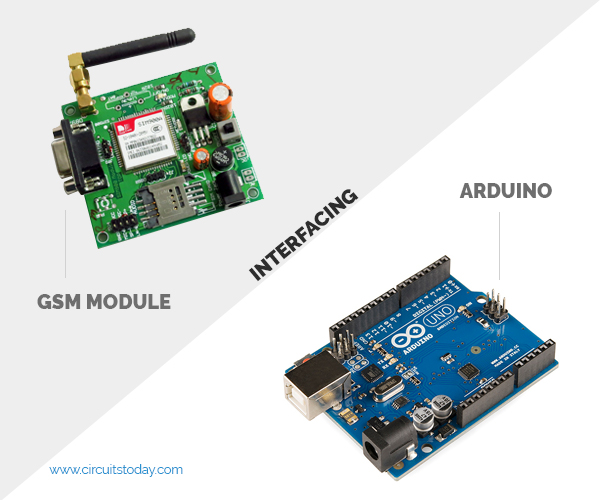
Booting the GSM Module!
1. Insert the SIM card to GSM module and lock it.
2. Connect the adapter to GSM module and turn it ON!
3. Now wait for some time (say 1 minute) and see the blinking rate of ‘status LED’ or ‘network LED’ (GSM module will take some time to establish connection with mobile network)
4. Once the connection is established successfully, the status/network LED will blink continuously every 3 seconds. You may try making a call to the mobile number of the sim card inside GSM module. If you hear a ring back, the gsm module has successfully established network connection.
Okay! Now let’s see how to connect a gsm module to Arduino!
Connecting GSM Module to Arduino
There are two ways of connecting GSM module to arduino. In any case, the communication between Arduino and GSM module is serial. So we are supposed to use serial pins of Arduino (Rx and Tx). So if you are going with this method, you may connect the Tx pin of GSM module to Rx pin of Arduino and Rx pin of GSM module to Tx pin of Arduino. You read it right ? GSM Tx –> Arduino Rx and GSM Rx –> Arduino Tx. Now connect the ground pin of arduino to ground pin of gsm module! So that’s all! You made 3 connections and the wiring is over! Now you can load different programs to communicate with gsm module and make it work.
Note:- The problem with this connection is that, while programming Arduino uses serial ports to load program from the Arduino IDE. If these pins are used in wiring, the program will not be loaded successfully to Arduino. So you have to disconnect wiring in Rx and Tx each time you burn the program to arduino. Once the program is loaded successfully, you can reconnect these pins and have the system working!
To avoid this difficulty, I am using an alternate method in which two digital pins of arduino are used for serial communication. We need to select two PWM enabled pins of arduino for this method. So I choose pins 9 and 10 (which are PWM enabled pins). This method is made possible with the SoftwareSerial Library of Ardunio. SoftwareSerial is a library of Arduino which enables serial data communication through other digital pins of Arduino. The library replicates hardware functions and handles the task of serial communication.
I hope you understood so far! Lets get to the circuit diagram! So given below is the circuit diagram to connect gsm module to arduino – and hence use the circuit to send sms and receive sms using arduino and gsm modem.
For more detail: How to Interface GSM Module to Arduino-Send and Receive SMS