MOTTO OF GESTURE CONTROLLED CAR:
- To drive a toy car using our hand movements or gestures.
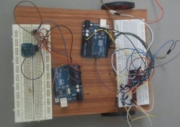
HARDWARE USED:
TRANSMITTER PART AND ROBOT:
- Arduino Uno.
- ADXL335 accelerometer.
- 434 MHz RF transmitter.
- Breadboard.
RECEIVER PART AND ROBOT:
- Arduino Uno.
- 434 MHz RF receiver.
- L293D motor driver IC.
- Chassis and wheels.
- 2 DC motors.
- Breadboard.
SCHEMATIC DIAGRAM OF TRANSMITTER:
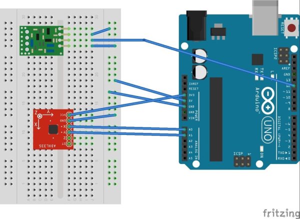
ADXL335:
This forms the basic constituent of our gesture controlled car. This basically is an Accelerometer which is capable of detecting acceleration in three axis X,Y and Z. The output of these three axis can be obtained separately from three pins x,y and z. This is shown in the above circuit diagram (I have used only X and Y axis for this project) . Read briefly about interfacing this sensor with Arduino here.
ARDUINO UNO:
The arduino board in the transmitter part acts as an interpreter. This fetches X and Y values from the accelerometer and then decides the gesture. There are five gestures or movements we have used in this project. By trail and error method we have recorded the X and Y values for the gestures, those are
- Stop or No Movement – X-Value:331 to 339 & Y-Value:341 to 349
- Tilt Forward or Forward movement – X-Value:376 to 384 & Y-Value:336 to 344
- Tilt Backward or Backward Movement – X-Value:301 to 309 & Y-Value:351 to 359
- Tilt Left or Left movement – X-Value:291 to 299 & Y-Value:276 to 284
- Tilt Right or Right movement – X-Value:316 to 324 & Y-Value:386 to 394
Based on the above conditions the Arduino will decide the movement and send it to transmitter.
433MHZ TRANSMITTER:
This is one of the popular plug and play RF module which comes with a RX pair. It transmits the command received from Arduino and transmit it to rx module at a frequency of 433Mhz.
Read More: Gesture controlled car using Arduino