Summary of BJT In Reverse Avalanche Mode
The article discusses using bipolar junction transistors (BJTs) in their reverse avalanche region, termed "negistors," to create fast pulse generators. By reversing collector and emitter connections, the transistor avalanches at lower voltages due to junction asymmetries. A simple LED flasher circuit demonstrates this behavior, where a capacitor charges until breakdown triggers rapid discharge through the LED, causing blinking. The blinking frequency depends on the RC values and transistor characteristics. Testing various transistors revealed their differing reverse avalanche voltages. This principle can be used in pulse generation and LED flasher applications.
Parts used in the LED Flasher Circuit:
- Bipolar Junction Transistor (various types tested, e.g., 2N3904)
- Capacitor
- Resistor (current limiting)
- LED (typical 5mm white LED)
Transistors operating in their avalanche regions are often used to generate fast rise pulses (seeavalanche pulse generator using 2N3904). Many transistors can also avalanche when the connections to collector and emitter are reversed. When operating in reverse avalanche region, these transistors are sometimes referred to as negistors.
Because the asymmetry and doping differences between the base-emitter and base-collector junctions, the avalanche voltages for reversely connected BTJs are usually magnitudes lower than their normal avalanche voltages. Here, I decided to test a few different transistors and see at what voltages the reverse avalanche occur.
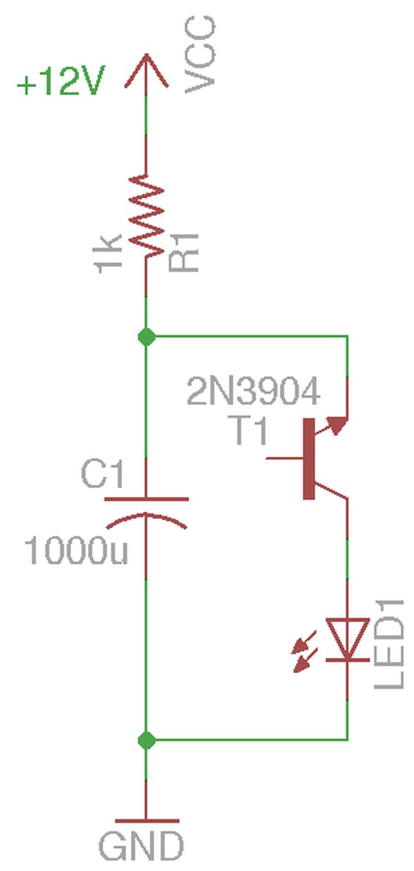
The circuit I used is a simple LED flasher, similar to what was described here. As with any circuit that exhibits negative differential resistance, the principle of operation is quite simple. The capacitor is charged via a current limiting resistor. When the voltage is low, the current that flows between the emitter and collector is roughly the reverse current of a diode which is negligible. When the voltage across the capacitor reaches a certain level, the transistor enters the avalanche breakdown mode. In its avalanche breakdown region, the transistor exhibits negative resistance (i.e. the higher the current, the lower the resistance) so the capacitor discharges rapidly through the LED and the voltage across drops until the avalanche mode can no longer be sustained. At such point, the transistor enters its normal operation mode and becomes non-conductive again. Thus the cycle continues. The rapid discharging through the LED manifests itself as short blinks. The blinking frequency largely depends upon the RC constant and the transistor breakdown characteristics.
Depending on the LED you use, you may need to add a current limiting resistor to protect the LED during discharge. But for a typical 5mm white LED, no resistor is needed as the duration of the current flow is extremely short.
Using the RC values in the schematic above, I measured the minimum voltages required for the circuit to oscillate using different transistors and the results are listed below:
For more detail: BJT In Reverse Avalanche Mode