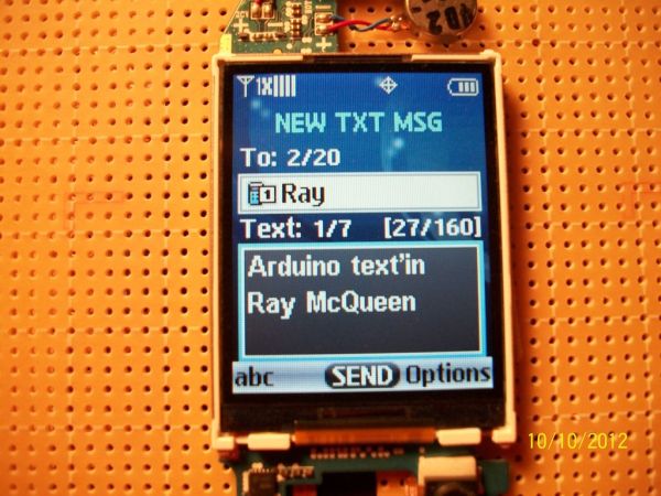
Arduino text‘in.
Key Features:
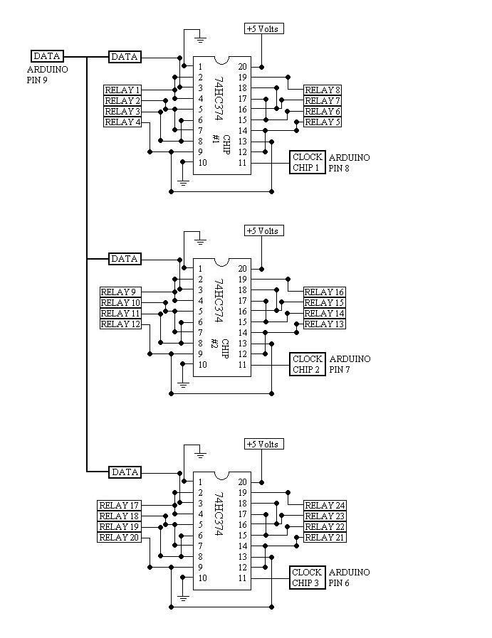
24 relays controlled by 4 I/O lines!
Cell phone text using your Arduino.
This project hacks a cell phone to text using normally open relays. After investigating cellular modules on the internet I decided it looks not only rather pricy, but also like a possibility that even after I had it working that a cellular provider might not let me put the device on their network. It seemed like a good cell phone hack was in order to make this work for me.
Step 1:
Purchase a cheap prepaid flip phone, activate and charge it. Mine was $20.00.
Flip phones are fairly easy to disassemble. You will need a very small screw driver set. The button pads on the inside are still large enough to allow for soldering wires in place without too much trouble. The prepaid plans let you text for pretty cheap too if you pick the right plan. Plus because its prepaid you can just let it run out whenever you are finished with it and best of all no contract.
Turn on the flip phone and take some notes about how it operates. Yours may access menus and things differently then mine does and its nice to know as you move forward with this.
Figure out what keys you still want to have access to once the phone is mounted. Because I used a prepaid phone I have to access it now and then to add more air time. It is also helpful to know how things are going with the phone when you can turn it on and activate it with the buttons after it is mounted to the board. The buttons on your cell phone board will be connecting directly to the phone. This way you can access the phone even if the rest of the circuit is off or maybe just doing other things.
Safety First. Remove the battery from the phone. Tear apart the flip phone. The circuit board inside is pretty delicate and has some sharp parts so use some caution. Do not break the LCD displays and be very careful not to destroy the very small ribbon cables that interconnect things. The part of the phone that houses the LCD, microphone and usually the camera will need to be taken completely out of the case. The flip phone I purchased had enough room to flip the camera around so that it can still take pictures. The case for the main board of the phone (where the battery is) will need to stay more or less intact. This makes it easier to put the battery back in and your not messing with the built in antenna so it should still have its normal signal strength.
Step 2:
1 – Arduino Uno
24 – Normally Open buttons. These will replace the buttons on the phone.
3 – 74HC374 Octal D-Type Flip-Flop chips.
24 – Reed relays. I had a bunch laying around.
24 – NPN general purpose. I used 2N2222.
24 – 20 K Ohm resistors
24 to 48 General purpose diodes
You don’t have to go overkill like I did. At minimum you need one diode across the relay coil to prevent voltage spikes when the coil turns off.
1 – Board to mount relay stuff.
1 – Board to mount cell phone
A bunch of jumper wires. Keep them neat. It makes it easier to trouble shoot.
1 – 12 volt power for relays.
1 – 5 volt power for 74hc374’s and Arduino.
Step 3:
Layout your buttons on your board more or less like they are laid out on the cell phone. This makes it easier to know what buttons you are pressing. Notice that I have not used a few of the buttons.
Step 4:
Find some small fairly flexible cable to use for all of the interconnecting soldering you are going to be doing. I used some spare ribbon cable. I cut it longer then I would need. I then tinned and trimmed the end to go to the phone. Leave your wires long here because it is easier to cut wire off then it is to try to re-solder them. The circuit board on the phone can easily be damaged by too much heat so use caution. I found it easier to start with the button pads closest to my new buttons and move my way up from there.
Step 5:
Once you have the part of the phone that houses the LCD apart you may need to cut or drill a hole in the mounting board for the ribbon cable to go through. The LCD will be mounting on the same side as the new buttons. I used some two sided tape to mount it. The main part of the cell phone will be mounted on the other side so it is closer to the relays.
1 – Arduino Uno
24 – Normally Open buttons. These will replace the buttons on the phone.
3 – 74HC374 Octal D-Type Flip-Flop chips.
24 – Reed relays. I had a bunch laying around.
24 – NPN general purpose. I used 2N2222.
24 – 20 K Ohm resistors
24 to 48 General purpose diodes
You don’t have to go overkill like I did. At minimum you need one diode across the relay coil to prevent voltage spikes when the coil turns off.
1 – Board to mount relay stuff.
1 – Board to mount cell phone
A bunch of jumper wires. Keep them neat. It makes it easier to trouble shoot.
1 – 12 volt power for relays.
1 – 5 volt power for 74hc374’s and Arduino.
For more detail: Cell phone text using an Arduino