
Summary of Zero-wire serial auto-reset for Arduino
### Article Summary This article details a DIY method to enable auto-reset functionality on Arduino Pro Mini boards when using TTL serial adapters that lack a DTR line. The solution utilizes the existing 0.1uF capacitor and modifies the circuit by relocating a chip resistor and adding a diode between the RXD and RST pins. This RC configuration ensures the board resets only when the serial line stays low for over 100ms, distinguishing it from normal short data bursts, effectively replicating the standard auto-reset feature without extra hardware complexity.
Parts used in the Zero-wire serial auto-reset project:
- Arduino Pro Mini board
- Existing 0.1uF capacitor
- Chip resistor (10kOhm or 11kOhm)
- Diode
Various versions of the Arduino will reset the board by toggling the serial DTR line, a feature called auto-reset. Since it relies on the DTR line, it won’t work with TTL serial adapters that don’t break out the DTR line. After writing my half-duplex serial UART, I thought of using the TTL serial break signal which holds the line at 0V for several ms. Normal serial communications would also send 0V, but at 57.6kbps, it would never last more than 160us before returning to the idle high voltage state. So what I needed was a circuit would not reset when the line is low for 160us, but would reset when the line is low for 100ms or more.
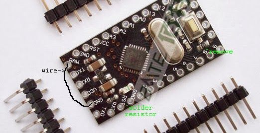
This can be done with a simple Resistor-Capacitor or RC circuit. The time for a capacitor to discharge by 63% is equal to the resistance in ohms times the capacitance in farads. Picking a common 0.1uF capacitor and a 10kOhm resistor gives an RC time constant of 1ms, high enough above the 160us time to provide a good safety margin. Another reason for picking those values is that most pro mini boards, including the Baite Pro mini I recently purchased, use those values for the DTR auto-reset feature. My plan was to make use of the existing components for my auto-reset circuit. I also needed a way to quickly charge the capacitor, since the idle time between bytes won’t be long enough to fully charge the capacitor through the resistor. A diode serves that purpose, so the whole circuit takes just 3 parts.
The pro mini already has a 0.1uF capacitor in series between the DTR and RST line, so I shorted DTR to GND to make the connection between the capacitor and ground. I used tweezers to move the tiny chip resistor (actually 11kOhm on the Baite board) from near the button to the space between the RXD and RST pins:
- Why does the standard auto-reset fail with some serial adapters?
It fails because those adapters do not break out the DTR line required to toggle the reset. - How long must the serial line stay low to trigger a reset in this circuit?
The line must remain low for 100ms or more to trigger a reset. - What is the maximum duration of a normal 57.6kbps data burst before returning to idle?
A normal burst lasts no more than 160us before returning to the idle high voltage state. - What components are needed to build this specific auto-reset circuit?
The circuit requires just three parts: an existing capacitor, a relocated resistor, and a diode. - How is the capacitor charged quickly enough for rapid communication?
A diode is used to allow the capacitor to charge quickly since idle time between bytes is too short for charging through the resistor alone. - Where was the chip resistor moved on the Baite Pro Mini board?
The chip resistor was moved from near the button to the space between the RXD and RST pins. - Why were 0.1uF capacitors and 10kOhm resistors chosen for the values?
These values create a 1ms time constant, providing a safety margin above the 160us threshold and matching common Pro Mini designs. - How was the connection to ground established for the capacitor?
The user shorted the DTR pin to GND to connect the capacitor to ground.
