A while ago I needed some small value resistors as current shunts and I started wondering about the feasibility of using traces as resistors.
There are many theoretical reasons as to why copper traces make bad shunt resistors, but I found surprisingly little practical data.
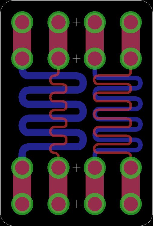
So with my next OSH Park order, I threw in a small test board:
The traces are (from left to right):
– 20 mil wide, 1221 mil long, should be ~30mOhms
– 6 mil wide, 611 mil long, ~50mOhms
– 12 mil wide 1221 mil long, 50 mOhms
– 6 mil wide 1221 mil long, 100 mOhms
As is standard with OSH Park I got 3 copies back.
My current test layout is fairly simple and probably not very accurate. The brain is an Arduino Micro, which controls a variable Voltage source. The output voltage is fed through one of the test traces into two 10 Ohm load resistors. The Arduino measures the voltage drop over the second resistor to guestimate the current flowing through the circuit.
An INA214 from TI is used to measure the voltage drop over the test trace and feed it into one of the Arduinos ADCs.
There is also some other support hardware (SD-card, LCD, NTC-temperature sensor, buttons,…).
While this setup isn’t very accurate, it should be fairly stable. The ADCs use the AVRs internal 2.56V reference and the voltage regulator output looks fairly consistent.
For more detail: Using Traces As Resistors

