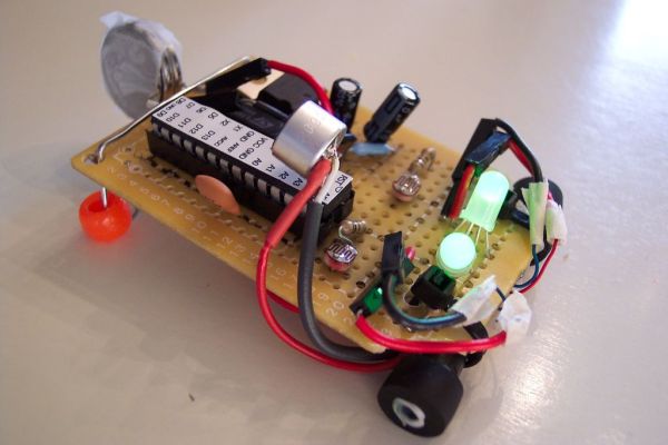
I love robots. Normally the ones I build are quite large and wouldn’t fit in your pocket, but for a change of pace I decided I would try something small and fun! This robot is exactly that, and in fact fits inside of an altoids tin. It is inexpensive, versatile (so many different sensors can be used), and extremely entertaining. Check it out in action below! (Unfortunately I played with mine so much before I took any video I had used up my coin cell batteries and one motor started having issues, so I’m driving it with a 9V in the video)
The project takes some time but teaches a lot about motor controllers, the ATMega chip, and soldering. The most fun thing was picking the different sensors and writing programs to have it react (only two of my four are shown in the video), as you can give the robot lots of ‘personality’ that way. Never a dull moment when you have this guy in your pocket!
Step 1: Parts List
Since this project is one that has many different possibilities I’ll mainly discuss the essential parts.
Essentials:
1 x Arduino (preferably UNO)
1 x ATmega328 chip (other versions work too, more on this later. You’ll most likely want one with a preloaded bootloader)
1 x 28 pin DIP socket (holds the ATMega, not absolutely necessary but you really should have it)
1 x 5v Regulator (L7805)
2 x 10 uf Capacitors
1 x 16Mhz Ceramic Resonator (a 16Mhz crystal works too, but you will need additional capacitors which take up space.
1 x pcb board (got a small one that fit in an altoid tin from radioshack for a few bucks)
1 x breadboard (to test the circuit)
2 x motors (I used pager motors with planetary gear boxes from robotshop.com)
2 x wheels (also got these from robotshop.com, but you can use whatever works)
1 x L293D (motor driver chip, which is necessary if you will be using motors)
1 x pushbutton (my code revolved around this thing, definitely useful)
Wires! Will need a lot to breadboard and solder.
Coin cell batteries (these keep the size small enough to fit in the altoids tin)
Fun Extras:
2 x photoresistors (lots of fun programs you can write for these)
2 x RGB LED’s (gives it the personality!)
1 x mic element (lets it listen and react to sound)
Anything you think would be cool! I wanted to add sound, but sadly didn’t have enough space left for a tiny piezo speaker.
Tools: clippers, soldering iron, perhaps a friend to help hold wires
Step 2: Main Circuit
There are two main circuits: one for the motor controller (L293D) and the ATmega328 chip.
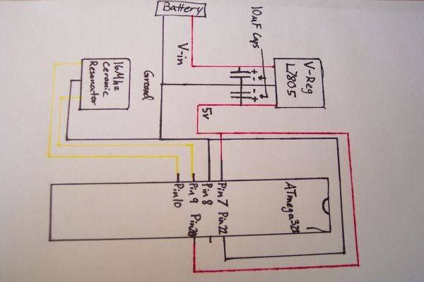
You can find a pinout diagram of the ATmega328 courtesy of instructablesHERE. Basically you are making the simplest arduino circuit possible (I don’t even include a reset button, but you can if you’d like). Now the only things you will HAVE to hook up to the ATmega is 5v (regulated by the L7805) to pins 7 and 20, ground to pins 8 and 22 (i drew in pin 21 as blank because it doesn’t need to be connected to anything), and the ceramic resonator (or crystal oscillator) to pins 9 and 10. See the pictures for how to use the capacitors with the voltage regulator and be sure to ground the middle pin of your ceramic resonator. If you are using a crystal oscillator you will need additional capacitors, to see how to do that or as another reference for any part of this circuit check the ‘ible HERE.
The pinout diagram for the L293D motor controller can be found HERE. I don’t have any pictures of this because it’s pretty simple pins 1, 8, 9, and 16 get 5v; pins 2, 7, 10, and 15 go to the arduino digital pins (I used ones with pwm to control motor speeds); pins 3, 6, 11, and 14 are hooked up to the motors (the motors run of 3v but the drop through the chip is enough that no diode’s are needed); and pins 4, 5, 12, and 13 are put to ground.
Step 3: Extras
These are really up to you, I will show you some simple circuits for the things I added but be creative! This is what gives the robot its ‘personality’ and makes it interesting.
Step 4: Testing
This is a vital step. You will need to breadboard your entire circuit layout. For now just wire all the sensors and motors up to an actual Arduino because repeatedly taking out the chip to stick in the breadboard would be quite a pain. Once you have done that and written your code (for reference and fun, my program can be found HERE) you can remove the ATMega328 chip from the Arduino and place it into your breadboard. Be extremely cautious when doing this as it requires lots of force and is easy to bend the chip’s leads. Once it is in place in the breadboard, connect up the voltage regulator with capacitors and the ceramic resonator to the chip (follow the schematics talked about earlier) and make sure that the voltage is going to the chip at 5v and the program runs as it should free from the board.
Now you’re cookin’!
For more detai: Tiny Altoid Tin Robot With Personality


