Summary of RS232 – MAX232 Interface Module
This article describes a compact RS232 Interface Board centered on the MAX232 IC, designed to convert microcontroller signals for computer serial port communication. It handles voltage level shifting between 5V and 12V DC, featuring a 9-pin female D-sub connector for host connection and header pins for data transmission (TXD) and reception (RXD). The board measures 40mm x 33mm, includes four mounting holes, and draws 50mA from a 5V supply provided by the host interface.
Parts used in the RS232 Interface Board:
- MAX232 Level Shifter IC
- 9 pin female D connector
- Connector J1
- Relimate/Header connector
- PCB (40 mm x 33 mm)
- Four mounting holes of 3.2 mm each
This project is a RS232 Interface Board based on MAX232 IC.
Description
This project provides you a simple and easy solution to connect / convert your Microcontroller input/output to be connected to the serial port of the Computer.
This projects build around popular MAX232 level shifter IC to do the Level Shifting (Voltage) between 5 V and 12 V DC.
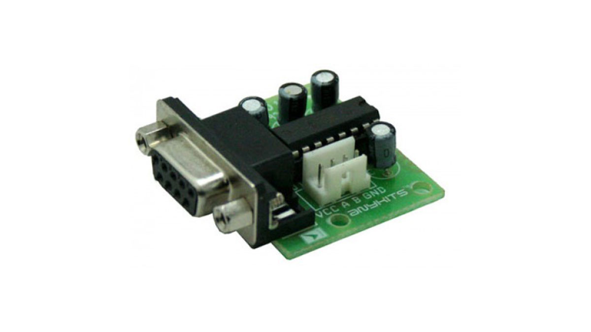
An Onboard 9 pin female D connects this PCB to the Serial Port cable (not supplied with the Kit). Connector J1 connects to the Host for power supply and serial In/Out signals.
A Provides data from the Computer to the Host (RXD)
B Provides data to be sent to the Computer from the Host (TXD)
Specifications:
Supply 5V DC @ 50mA
MAX232 based Level Shifter IC
Simple and straight forward design
Easy connection via relimate/Header connector to your HOST interface
Supply provided by the host interface
Four mounting holes of 3.2 mm each
PCB dimensions 40 mm x 33 mm
For More Details: RS232 – MAX232 Interface Module
- What is the main function of this project?
This project provides a simple solution to connect or convert Microcontroller input/output to be connected to the serial port of the Computer. - Which IC is used for level shifting in this design?
The project builds around the popular MAX232 level shifter IC to do the Level Shifting between 5 V and 12 V DC. - How does the board connect to the computer?
An Onboard 9 pin female D connects this PCB to the Serial Port cable via Connector J1 which connects to the Host. - What are the functions of pins A and B?
Pin A provides data from the Computer to the Host as RXD, while Pin B provides data to be sent to the Computer from the Host as TXD. - What power supply is required for operation?
The specifications require a Supply of 5V DC at 50mA, which is provided by the host interface. - Can I mount this board easily?
Yes, the board features four mounting holes of 3.2 mm each for easy installation. - What are the physical dimensions of the PCB?
The PCB dimensions are 40 mm x 33 mm. - Is the serial port cable included with the kit?
No, the kit does not supply the Serial Port cable needed to connect to the 9 pin female D connector.