As a Water Quality professional working in the drinking water field, I know how important it is to accurately monitor the disinfectant levels in the drinking water that gets served to the public. Usually, that means taking weekly grab samples in the distribution system and measuring free chlorine or total chlorine residual via a DPD colorimetric test. Sometimes, however, it would be nice to know what’s going on with the disinfectant residual when you’re not out there to take a sample. It would be nice to log the residual over time. That’s why I wanted to put together an inexpensive data logger that would measure and log pH, oxidation-reduction potential (ORP), and temperature. From those three parameters, the disinfectant residual can be approximated, not to mention that they are interesting parameters to measure and log in their own right. In my research for this project, I also came across some other uses in which this device might come in handy. It seems that aquarists regularly measure these parameters to keep their aquariums healthy, and it can also be used to keep track of oxidant levels in apool or spa. These are three very commonly measured parameters in water system security devices that are being used more and more to make sure that a water system is not being tampered with. And, it can be used in the lab for testing oxidant dosing, or measuring reaction kinetics.
My criteria for the project were that it had to be fairly easy to make; relatively inexpensive; and pretty accurate. I think what I’ve created meets those criteria, and I hope you do, too!
Step 1: Parts and Supplies
[box color=”#985D00″ bg=”#FFF8CB” font=”verdana” fontsize=”14 ” radius=”20 ” border=”#985D12″ float=”right” head=”Major Components in Project” headbg=”#FFEB70″ headcolor=”#985D00″]
Here are the materials I used in my project, and where I purchased them:
1. Arduino Uno: http://stores.ebay.com/lemonbleue/
2. Prototyping Shield: http://stores.ebay.com/chippartnerstore/
3. pH probe: http://stores.ebay.com/lotsgoods88/
4. ORP probe: http://stores.ebay.com/eseasongear/
5. pH & ORP circuits: https://www.atlas-scientific.com/embedded.html
6. BNC connectors: https://www.atlas-scientific.com/embedded.html
7. Temperature sensor: http://www.ebay.com/usr/saymlove
8. LCD keypad shield: http://stores.ebay.com/womarts/
9. SD card shield: http://stores.ebay.com/csmqshop/
10. 170 tie point breadboards: http://stores.ebay.com/chippartnerstore/
11. Nylon mounting hardware: http://stores.ebay.com/audiowind2010/
12. Project box: http://www.discountofficeitems.com/school-supplies/student-teacher-supplies/basic-school-supplies/pencil-boxes-pouches/advantus-super-stacker-stackable-pencil/p296171.html?q=pencil%20boxes
Various and sundry other parts were used, such as all the jumper wires, were purchased from e-bay vendors and other electronic supply companys.[/box]
Step 2: Construction – Electronics
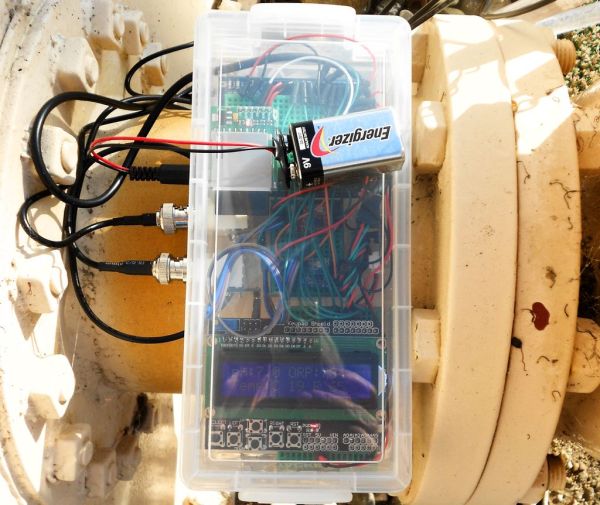
I have attached a diagram of the Fritzing wiring diagram for this project as a pdf. It isn’t laid out exactly like it is in my project box – the diagram utilizes a large breadboard instead of a prototyping shield and a smaller breadboard; and the LCD shown isn’t the exact one I had, nor is the temperature sensor. Also, I couldn’t find Fritzing library files for the Atlas Scientific pH and ORP circuits, so I had to make my own for illustrative purposes, as well as modify the BNC connectors I could find. But the diagram does show what wires I have hooked up to which pins on the Arduino, which is the important part to get it to all working right with the programming. I used an LCD with a keypad because that’s what I had lying around; the keypad isn’t used, however, so you can just use any 16×2 LCD without the keypad.
I got everything to work together outside of the project box first, then disassembled it and put it back together inside the box. For the LCD, I took a 170 tie point breadboard, cut it in half along the middle spacer, and then used half for each side of the LCD. I mounted the pH and ORP circuits on another small breadboard and cut holes in the side of the plastic project box for the BNC connectors to stick through, connecting the BNC connectors to the breadboard with the pH and ORP circuits with jumper wires. I did the same for the USB and power connectors for the UNO, and for the temperature probe. I also drilled some small holes on the back of the box to put small nylon screws through to secure the UNO and the temperature circuit.
Step 3: Construction – Sample Cell
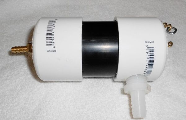
The probes, of course, have to be in contact with the solution being sampled. If the unit is being used in the laboratory, you can just immerse them in the container, such as a beaker or an Erlenmeyer flask, or use a probe holder. If your doing work in the field, you may need a sample cell to put the probes in, and then run the water through that. The sample cell I built for this purpose is very simple. I used a 2″ diameter piece of PVC pipe with caps on the end. In one end, which will be the bottom, I drilled a hole and inserted a barbed fitting for 1/4″ ID hose. This will be the water inlet. On the other end, I drilled a small hole for the temperature probe, and two 1/2″ diameter holes for the pH and ORP probes. On the side near the top, I drilled a hole for a barbed fitting for a 1/2″ ID hose. This will be the outlet for the water being sampled. The small diameter hose is attached to the water source, which is turned on at a very low rate of flow. The water flows into the flow cell through the bottom and overflows through the larger fitting on the side near the top. The water level is sufficient to keep the probes continuously covered. I added a couple of eye screws and a length of chain at the top to help secure the sample cell in the field.
For more detail: ORP / pH / Temperature Data Logger


