Summary of High efficiency regulated Joule thief
The author built a regulated Joule thief to provide stable voltage for small devices, avoiding the efficiency loss of Zener diodes. Using salvaged parts from a defective LED bulb and new components like an NPN transistor and NMOS switch, the circuit achieves a controlled output without constant DC current drain. The design employs a bipolar Schmitt trigger and variable resistor divider to regulate voltage via an NMOS switch connected to the oscillator's base.
Parts used in the Regulated Joule Thief:
- Ferrite toroidal transformer (from LED bulb)
- Ferrite bead
- Enamelled wire (~1 meter)
- NPN transistor (2N2222)
- NMOS switch transistor
- Bipolar transistor Schmitt trigger
- Variable resistive voltage divider
- AAA battery (1.2V)
- Filter capacitor (2.2uF)
Normally the Joule thief produces output voltage, which value is difficult to predict. Without load (the LED) I have measured voltages over 30 V. I wanted to create a Joule thief, which can be used to supply some small electronic devices, but having well defined and stable output voltage. There are known some solutions in which instead the LED load, a one-diode rectifier is used, and the output voltage is stabilized by the use of Zenner diode. I did not like this solution, because through the Zenner diode flows always a constant DC current, what reduces drastically the efficiency of the device and empties fast the supply battery. I was looking for other, better solution of the output voltage stabilization (limitation).
To try my solution, at first, I needed to build the standard working Joule thief. How to do this – there are a lot of articles and internet sites (for example this). How to find the needed parts? – I knew that inside the high efficiency lighting bulbs are some parts, which could be re-used. I had a defect bulb and I carefully cut the plastic box. From there I extracted the voltage converting board. On these PCB’s can be found some very useful stuff : HV diodes, chokes, HV capacitors, HV transistors..etc (HV means high voltage ~ 400V). I took the ferrite toroidal transformer, cut and removed all its wires.
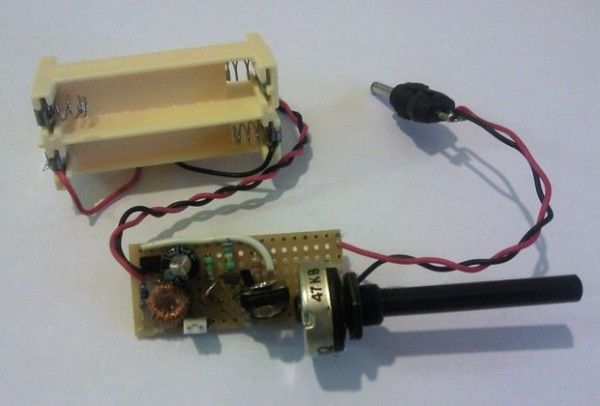
After that I disassembled the choke. I took around one meter enamelled wire from it, and winded it around the ferrite bead. Because the wire was fold, I winded simultaneously two coils having ~ 50 turns. Having the main part of the Joule thief (the transformer) ready, the remaining work is not much.. The only tricky in the design is to connect both coils in the correct way. (see the mentioned link for additional information). So designed the Joule thief was able to produce 34 V voltage measured on the collector node of the NPN transistor (2N2222) without any load, when supplied by 1.2V AAA battery (filterd with 2.2uF capacitor).
Step 1: The regulating circuit
After finishing the original Joule thief, I have created the additional circuit, which controls the output voltage. It is based on the use of bipolar transistor Schmitt trigger. Its input is connected to the middle point of variable resistive voltage divider placed between the regulated supply voltage and the common ground node.The output of the Schmitt trigger connects to the gate of NMOS switch transistor. The drain terminal of this switch connects to the base of the Joule thief oscillator transistor.
For more detail: High efficiency regulated Joule thief
- Why did the author reject using a Zener diode for stabilization?
A Zener diode allows a constant DC current to flow, which drastically reduces efficiency and empties the supply battery fast. - How was the ferrite toroidal transformer obtained?
The author extracted it by cutting open a defective high-efficiency lighting bulb and removing its voltage converting board. - What is the purpose of winding two coils simultaneously with folded wire?
This method creates two coils with approximately 50 turns each around the ferrite bead for the transformer. - How does the regulating circuit control the output voltage?
It uses a bipolar transistor Schmitt trigger connected to a variable resistive voltage divider to control an NMOS switch. - Where does the output of the Schmitt trigger connect?
The output connects to the gate of the NMOS switch transistor, whose drain connects to the base of the Joule thief oscillator transistor. - What voltage was measured on the collector node without load?
The circuit produced 34 V on the collector node of the NPN transistor when supplied by a filtered 1.2V AAA battery. - Which specific NPN transistor was used in the oscillator?
The design utilized a 2N2222 NPN transistor. - What component filters the input power source?
A 2.2uF capacitor is used to filter the 1.2V AAA battery supply.