Summary of DIY Teagueduino
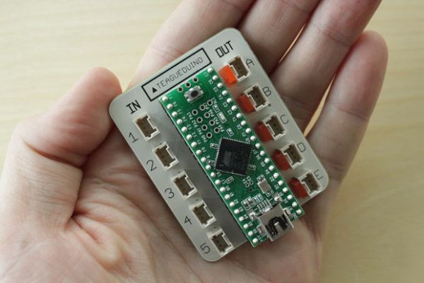
Teagueduino is an open-source electronic board enabling users to build creative projects without soldering or coding skills initially, while teaching embedded development. This guide details how to assemble a DIY Teagueduino board by soldering components onto a custom PCB, including a 40-pin socket and mini-CT connectors.
Parts used in the DIY Teagueduino:
- Teagueduino PCB
- 40-pin socket
- 10 3-pin mini-CT connectors
- 5 LEDs
- Eagle files for PCB design
- Teagueduino circuit schematic
What is Teagueduino?
Teagueduino is an open source electronic board and interface that allows you to realize creative ideas without soldering or knowing how to code, while teaching you the ropes of programming and embedded development (like Arduino). Teagueduino is designed to help you discover your inner techno-geek and embrace the awesomeness of making things in real-time — even if you’ve only ever programmed your VCR.
This project we originally created by Teague, and was fully backed by supporters on Kickstarter (check out the detailed Teagueduino post on Kickstarter here). We made 300+ kits, and now we want to open it up for the world to make, too!
In this instructable we’ll show you how to solder up your very own Teagueduino board. Enjoy 🙂
Step 1: Get the parts
To get started, you’ll need some parts.
See the Teagueduino bill of materials for part numbers and links to order from DigiKey. Get everything in the first section, and note the quantity of each (for example you’ll need 10 connectors, and 5 LEDs).
Perhaps the trickiest part is the Teagueduino PCB. We’re hoping to make blank Teagueduino PCBs available in the future, but until then feel free to make your own Teagueduino PCB from the Eagle files.
And if you curious what’s happening electrically, take a look at the Teagueduino circuit schematic.
Step 2: Solder in the socket
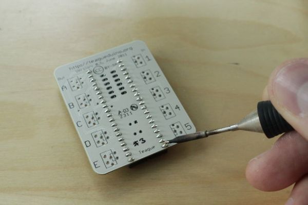
First, get out the PCB.
Add the 40-pin socket (notice that the notch is near the edge of the board). Carefully solder it on the back of the board. A couple of the pins will be more difficult to solder because they are connected to the power/ground planes and quickly diffuse the heat from the soldering iron. Just be patient.
Step 3: Solder in the connectors
Now add the 10 3-pin mini-CT connectors.
Note that you can slightly bend the pins such that the connectors will snap into the PCB nicely. This is handy so that they don’t fall out as you turn the board over to solder them in.
For more detail: DIY Teagueduino
- What is Teagueduino?
It is an open source electronic board allowing users to realize creative ideas without soldering or knowing how to code. - How can I get the parts for this project?
You need to see the Teagueduino bill of materials for part numbers and links to order from DigiKey. - Can I make my own Teagueduino PCB?
Yes, you can make your own Teagueduino PCB from the Eagle files until blank boards are available. - What is the first step in soldering the board?
The first step is to add the 40-pin socket with the notch near the edge of the board. - Why might some pins be difficult to solder?
Some pins are connected to power/ground planes which quickly diffuse heat from the soldering iron. - How many 3-pin mini-CT connectors are required?
You will need 10 3-pin mini-CT connectors for the project. - Can I slightly bend the connector pins?
Yes, you can slightly bend the pins so that the connectors snap into the PCB nicely. - Where can I find the circuit schematic?
You can take a look at the Teagueduino circuit schematic to understand what is happening electrically.