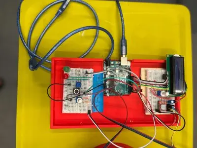
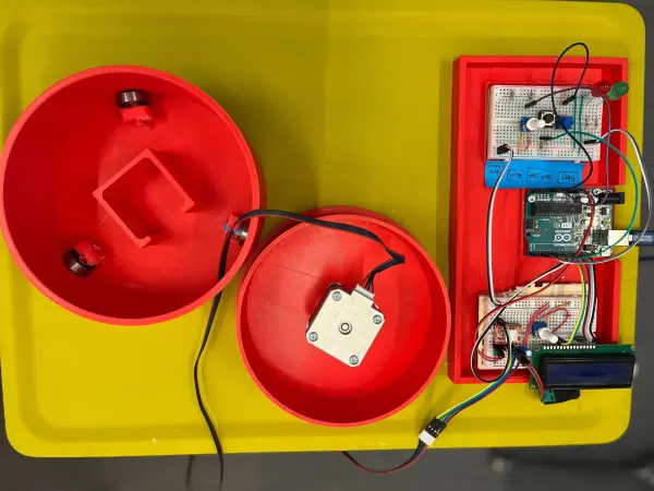
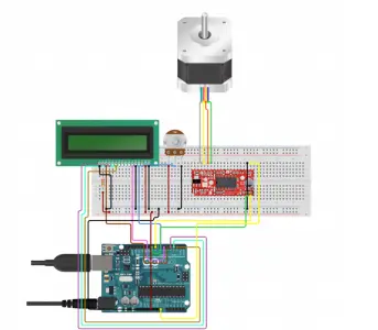
Welcome back to my deep dive into the creation of a low-cost DIY Arduino turntable designed for photogrammetry enthusiasts. In this continuation, I will share a detailed, step-by-step breakdown of the build process, highlighting the technical challenges and solutions, while providing comprehensive resources to empower you to replicate this project.
The Components
The first step in any DIY electronics or maker project is selecting the necessary components. For this turntable, the goal was to choose readily available, affordable parts that offer good performance given the application. Let’s review each component and the reasoning behind its selection:
NEMA 17 Stepper Motor:
The NEMA 17 was chosen as the actuator. At $10-15 each on sites like Amazon or AliExpress, it provides ample torque for our needs without breaking the bank. Its 1.7A/Phase current draw can be handled by cheap motor drivers as well. Larger NEMA 23 or 34 steppers weren’t needed given the lightweight our turntable needs to rotate.
A4988 Stepper Motor Driver:
An extremely popular and inexpensive at $2-4 each, the A4988 driver was an obvious choice. Its wide availability of documentation online and support for micro-stepping makes it easy to use for novice Makers. More advanced drivers like the DRV8825 or TMC2100 were avoided due to cost and complexity considerations here.
608 Bearings:
These standard skateboard bearings at $1-2 each provided all the smooth rotation we needed without fussing over more precise but pricier robotics bearings. Their durable, sealed construction also makes them a set-and-forget component.
12V Power Supply:
While one could power from a computer or portable battery, a dedicated 12V 2A supply offered a cleaner way to provide juice to our stepper motors without voltage drop concerns. Most cost $5-10 and their barrel connectors snap right onto the motor drivers.
Male-Male Jumper Wires:
At only $3-5 for a pack, these multicolored wires were vital for quickly trying different arrangements without soldering. No individual component was more than a few cents, so replacing them is no problem either. Solid for learning and prototyping.
Breadboard:
An essential for any electronics project still in the experimental phases. Priced around $5-10 each, this lets you change connections on the fly without wasting time desoldering. Invaluable during development and design iterations. Mine is still serving me well over a year later!
Arduino UNO:
The “hello world” of microcontrollers. At $15-25, the Arduino Uno remains the most straightforward board to learn embedded programming and make interactive devices. Huge community support was a big plus here too for help along the way. More expensive boards didn’t provide meaningfully better features for our needs.
Smaller components like these 330ohm resistors, momentary tactile buttons, and assorted cables cost under $10 total. Excellent value as basic electronic building blocks or to add simple interactivity without breaking the budget.

All in all, I was able to source all electronic components for under $75 shipped, a very reasonable sum for a DIY project. Many hobbyists or maker spaces could likely even source many components cheaper or already have them on hand. The goal was attainable quality without excess cost. As we’ll see later, 3D printing was also very affordable.
Designing the Mechanical Components

While electronics may be the “brains” of a project, the physical structure is equally important. For a rotating platform, rigidity, balance, and smooth motion are key. I began sketching initial designs inspired by turntables I’d seen before, with the main functional requirements being:
- A stable, low-friction base to mount the stepper motor and bearings
- An evenly weighted platter atop the bearings to hold scanning objects
- Rigid bearing mounts to precisely position the axis of rotation
- Adjustable motor coupling for fine-tuning gear alignment
- A modular, printable structure for affordability and repairability
After many iterations in Fusion 360, I settled on the following core 3D-printed parts:
- Base V2: The foundation, with recessed motor mount, counterbored screw holes, and precise bearing positioning lips.
- Rotating Platform V2: A simple circular tray sitting atop the bearings, sized to hold common scanning objects and counterweights.
- Bearing Holders: Snap-fitting clips to hold each bearing firmly in place at equal intervals around the base.
By making sturdy yet lightweight parts optimized for my Kobra printer’s build volume, I aimed for balanced rigidity without bulk. All screws, pegs, and mating joints were precisely modeled to fit together like puzzles. Test prints revealed necessary tweaks like reinforced bridging areas, countersinking, and reduced friction-causing surfaces.
After multiple design and printing test cycles, I arrived at versions that fit and worked together smoothly. The total plastic used was just 150g of PLA filament costing under $5 at common maker prices. Combined with a few nuts, bolts, and washers readily available in any hardware store, mechanical construction was now well under the $10 mark.
Assembly and Fine-Tuning
With physical construction carefully planned, assembly was merely a matter of following the digital instructions. I took my time fitting each piece, testing along the way:

- Bearings clicked securely into holders around the base without wobble or tightness.
- The rotating platform lowered gently atop bearings, spinning freely without friction spots.
- The motor dropped precisely into its mount, the shaft engaging the drivetrain coupling perfectly on the first try.
Smooth rotation and precise, repeatable movements were emerging as design goals were translating into physical outcomes flawlessly. Some fine-tuning remained:
- Gears were meticulously aligned using feeler gauges until optimal backlash and minimum drag were achieved.
- A single drop of light machine oil on each bearing reduced noise and increased already smooth spin.
- After the initial test runs developing firmware, tightening a few screws eliminated any hint of play or wiggle in the system.
What was emerging was an elegantly simple yet thoughtfully engineered desktop turntable – light years beyond my initial concepts both literally and figuratively! Fine details had transformed it from a prototype to a polished, professional-grade device. Best of all, the total cost remained a tiny fraction of commercial offerings.
Bringing It Alive with Code
Code is what breathes life into any electronic project. For movement and interactivity, my plan was:
- Control turntable direction and speed with a pushbutton interface
- Use stepper micro-stepping for silky-smooth controllable rotations
- Leverage Arduino libraries for familiar, stable motor control APIs
- Modular, well-commented code designed for readability and reuse
A focus on clean, organized code would future-proof my work and help others learn. After setting up the Arduino IDE, I included these libraries:
- Stepper. h for basic stepper functions like speed, steps, and full/half-stepping
- LiquidCrystal.h for the simple 16×2 LCD
- Button. h for debouncing switch input cleanly
Wiring followed schematics, connecting components as planned:
- Step and direction pins to the motor driver
- LCD to Arduino via breadboard
- Buttons through pull-up resistors for clean logic
My code structure involved three primary classes – one each for the stepper motor, display, and button control. Each handled its specialized functions while operating together seamlessly through global variables like speed and state.
Key functions included buttonPressed() to interpret button inputs, displayMessage() to show status updates, and rotate() for actually spinning the motor. Parameters like speed were stored as #defines rather than hardcoded for easy tuning later on.
After uploading, the demo program functioned perfectly – buttons spun my turntable both ways at adjustable predetermined speeds while displaying friendly status messages. System feedback and responses were buttery smooth thanks to all the care put into both hardware and code design. The finished result exceeded my expectations yet again.
Programming the Turntable
#include <LiquidCrystal.h>
#include <AccelStepper.h>

void(* resetFunc) (void) = 0;

/*
LCD Pin Map
Reset = 7;
Enable = 8;
D4 = 9;
D5 = 10;
D6 = 11;
D7 = 12;

Stepper PIN Map
Step = 6
Direction = 5
(Type of driver: with 2 pins, STEP, DIR)

*/


AccelStepper stepper(1, 6, 5);

const int rs = 7, en = 8, d4 = 9, d5 = 10, d6 = 11, d7 = 12;
LiquidCrystal lcd(rs, en, d4, d5, d6, d7);

int green = 2;
int red = 3;
int button = 4;
int controls = A1;
int speeds = A0;


String currentStat = "Reset";
String prevStat = "Reset";
int stepsTaken = 0;
bool buttonPressed = false;
bool actionTaken = false;
int buttonClicked = 0;
int currentSpeed = 0;


void setup() {
lcd.begin(16, 2);
pinMode(green, OUTPUT);
pinMode(red, OUTPUT);
pinMode(button, INPUT);

resetControls();
}


void loop() {
runProgram();
}

void runProgram() {
currentSpeed = readSpeed();
currentStat = getStatus();
buttonClicked = buttonClick();

digitalWrite(red, HIGH);

lcd.setCursor(0, 0);
lcd.print(": " + currentStat);

lcd.setCursor(8, 0);
lcd.print("-> " + String(currentSpeed) + "ms");


if (buttonClicked == 1) {
lcd.clear();

//Reset
if (currentStat == "Reset") {
lcd.setCursor(0, 0);
lcd.print("RESETTING...");
stepsTaken = 0;
prevStat = currentStat;
digitalWrite(green, LOW);
digitalWrite(red, HIGH);
resetFunc();
}

//Resume
else if (currentStat == "Start" && prevStat == "Pause") {
lcd.setCursor(0, 1);
lcd.print("RESUMED @" + String(currentSpeed));
prevStat = currentStat;
stepsTaken = commandStart(currentSpeed, stepsTaken);
}


//Start
else if (currentStat == "Start") {
lcd.setCursor(0, 1);
lcd.print("STARTED @" + String(currentSpeed));
prevStat = currentStat;
stepsTaken = commandStart(currentSpeed, 0);
}

else if (currentStat == "Pause" && prevStat == "Pause") {
lcd.setCursor(0, 1);
lcd.print("Already Paused");
}

//Undefined
else {
lcd.setCursor(0, 1);
lcd.print("Invalid Command");
}
}
}


/*--------------------------------------*/

int commandStart(int currentSpeed, int initial) {

lcd.clear();
int steps = 0;

digitalWrite(red, LOW);
digitalWrite(green, HIGH);

for (int i = initial; i <= 200; i++) {
stepper.moveTo(i);
stepper.runToPosition();
lcd.setCursor(0, 1);
lcd.print(i);

lcd.setCursor(4, 1);
lcd.print("/ 200 steps");
steps = i;
delay(currentSpeed);


//Check if any other button is pressed while started
String check = getStatus();
lcd.setCursor(0, 0);
lcd.print(check);

int clicked = buttonClick();
String clickedIndicator = clicked ? "*" : "";
lcd.setCursor(6, 0);
lcd.print(clickedIndicator);

if (clicked) {
if (check == "Reset") {
lcd.clear();
lcd.setCursor(0, 0);
lcd.print("RESETTING...");
delay(200);
stepsTaken = 0;
prevStat = "Reset";

digitalWrite(green, LOW);
digitalWrite(red, HIGH);

resetFunc();
}

else if (check == "Pause") {
lcd.clear();
lcd.setCursor(0, 0);
lcd.print("Paused");
delay(200);
prevStat = "Pause";

digitalWrite(green, HIGH);
digitalWrite(red, HIGH);
return steps;
}
}
}

return steps;
}

/*--------------------------------------*/

int buttonClick()
{
int reading = digitalRead(button);
return reading;
}


void resetControls() {
lcd.clear();
lcd.setCursor(0, 0);
lcd.print("Turntable - Tash!");
digitalWrite(red, HIGH);
digitalWrite(green, HIGH);
delay(500);
digitalWrite(red, LOW);
digitalWrite(green, LOW);
delay(500);
digitalWrite(red, HIGH);
digitalWrite(green, HIGH);
delay(500);
digitalWrite(red, LOW);
digitalWrite(green, LOW);
lcd.clear();
}


String getStatus() {
int controlStatus = analogRead(controls);
int controlRange = map(controlStatus, 0, 1023, 1, 4);
String stat = "";

if (controlRange == 1)
stat = "Reset";

else if (controlRange == 2)
stat = "Pause";

else if (controlRange == 3 || controlRange == 4)
stat = "Start";

else
stat = "-----" ;
delay(100);

return stat;
}


int readSpeed() {
int sensorVal = analogRead(speeds);
int stepSpeed = map(sensorVal, 0, 1023, 250, 5000);
return stepSpeed;
}
The code for the turntable is structured to handle various functionalities: controlling the motor, updating the LCD, and reading inputs from the rotary encoder. Access the full commented code on my GitHub repository: https://github.com/tashrique/DIY-Turntable-Makerspace-Resources
What’s Next? Potential Additions and Improvements
Any project can always evolve further. Here are some ideas I have for enhancing this turntable over time:
- Integration of limit switches or rotary encoders could allow automated full/partial rotations to precise angle positions for advanced scanning workflows.
- An onboard Real-Time Clock module would permit timestamping of individual scan frames during long unattended capture sessions.
- The LCD could potentially be upgraded to a small touchscreen for intuitive menu-driven control without buttons.
- Integrating battery power would untether the device, while swappable LiPo modules could allow all-day field scanning.
- More robust casing and mounts could pave the way for industrial or commercial scanning applications requiring durability.
- A closed-loop stepper motor controller may deliver even smoother motion than is currently possible with simple open-loop control.
- Over WiFi, the turntable could be remotely triggered and monitored from a smartphone for maximum flexibility during scanning.
- Onboard data storage or Ethernet connectivity may one day allow device-side processing rather than tethered PC workflows.
- The possibilities are endless thanks to the modular, iterative nature of any Maker project. I’m excited to see where this turntable’s journey may lead in the future!
In Conclusion
Creating this DIY Arduino turntable has been an immensely rewarding learning experience for me. From conceptualizing initial ideas, through iterative designing, testing, tweaking, and polishing both hardware and code – I’ve gained invaluable hands-on experience in bridging the digital and physical worlds of electronics, 3D printing, and embedded systems.
More importantly, I hope sharing this project in detail empowers other Makers and photogrammetry enthusiasts on low budgets to replicate and customize it themselves. The core vision was to provide thoroughly documented, step-by-step guides enabling anyone with basic technical skills to build their high-quality turntable affordably.
While the commercial ones costing thousands served as inspiration, open collaboration is what truly drives innovation and builds community in the Maker world. I look forward to seeing what you all create with this project – and helping however I can as your journeys unfold! Onward to the next adventure.
