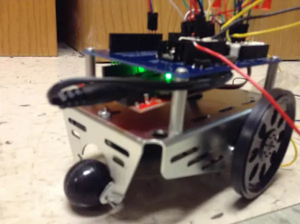
The accelerometer cart marks my second intermediate project creation. Essentially, it’s a compact robot designed to interpret signals from a triple-axis accelerometer, adjusting its movement direction accordingly.
Building the Accelerometer Cart
The Accelerometer Cart employs a triple-axis accelerometer to determine the direction in which the device is tilted. This data is then transmitted to a SparkFun Redboard, which subsequently controls two servo motors. These motors, in turn, rotate wheels in the appropriate direction, propelling the small robot chassis.
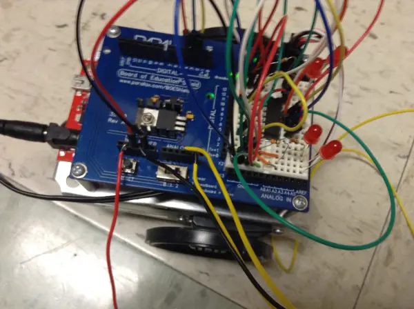
The robot chassis, originally sourced from a Parallax Inc Board of Education Shield provided by my instructor, features a metal body housing batteries and servos underneath. Additionally, it is equipped with a wheel attached to each servo and a rolling ball at the front for added stability. Atop the chassis sits a shield, providing ample space for the Redboard or Arduino to be easily integrated. This shield also incorporates a small breadboard for convenient attachment of additional components.
Moreover, the cart utilizes a shift register and LEDs to enhance its functionality. When the accelerometer tilts backward, indicating a movement toward the user, the cart reverses its direction, accompanied by the illumination of LEDs. Similarly, when the accelerometer is tilted sideways, LEDs on the corresponding side blink as the cart begins to turn in that direction.
Conceptualizing the Second Project
For my second project, I had the freedom to brainstorm ideas independently. Initially uncertain of the direction to take, I was drawn to the notion of leveraging a triple-axis accelerometer to control some form of motor. Although undecided on the specific device to pair with the accelerometer, I eventually settled on utilizing DC motors equipped with wheels, envisioning a device capable of movement based on the tilt of the accelerometer.
Discussing my concept with my instructor yielded approval, although the challenge of finding suitable wheels for the DC motors presented itself. Fortunately, my instructor recalled the availability of a robot chassis within the school’s resources. After confirming its availability, I opted to integrate a shift register and LEDs into the design to enhance its functionality.
Initially unsure of how to incorporate these components, I ultimately decided to utilize them as tail lights. With this final design in mind, the project took shape, culminating in the creation of a dynamic device driven by the tilt of the accelerometer.
Throughout the project development process, several challenges arose, requiring problem-solving and adaptability. One notable obstacle was the management of wire length, particularly in establishing sufficient distance between the accelerometer and the chassis while ensuring optimal functionality.
However, the most significant issue encountered pertained to intermittent disconnections of wires linking the accelerometer or the chassis, occasionally resulting in a wheel becoming stuck in motion. Although a simple reset typically resolves this issue promptly, ensuring secure connections of the accelerometer wires proves to be a more permanent solution. While this could potentially be attributed to a bug in the code, I am inclined to believe it primarily stems from loose wires.
Additionally, achieving proper functionality of the LEDs and shift register posed another challenge, requiring some troubleshooting to overcome. Furthermore, a minor delay introduced in the blinking mechanism, particularly in the “turn signal,” occasionally poses a slight inconvenience. Nevertheless, such occurrences are infrequent and do not significantly impact overall performance.
Constructing Your Own Accelerometer Cart
For those interested in assembling their own Accelerometer Cart, detailed instructions, including parts list, schematics, sketches, and code, are provided below.
Parts:
- (1) Arduino Uno/SparkFun Redboard
- (4) Red LEDs (color can be customized)
- (1) 74HC595 shift register
- (6) 330 Ohm resistors
- (1) MMA8452Q Triple-Axis Accelerometer
- (1) Parallax Inc BOE Robot (Alternatively, servo motors with attached wheels can be used, ensuring full rotation capability and proper support)
- Several wires, preferably long for added flexibility and convenience.
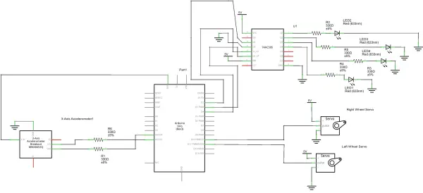
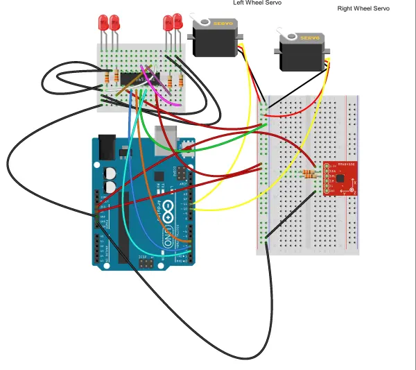
The basic schematic and sketch can be seen below:
Setting Up Components and Schematics
(Note: Due to limitations in the Fritzing software, the Parallax shield components are not available. Therefore, the sketches and schematics are configured as if connected directly to the servos.)
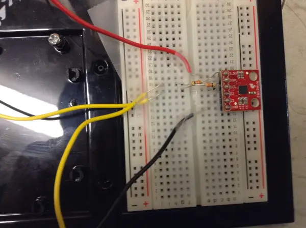
To begin, connect your triple-axis accelerometer by supplying power from the 3.3v pin on the Redboard to the corresponding pin on the accelerometer. Ground the accelerometer’s ground pin to the Redboard’s ground. Next, connect the SCL pin on the accelerometer to pin A4 and the SDA pin to pin A5, utilizing resistors as needed. These pins serve as substitutes for the absent SCL and SDA pins on the Parallax board.
For the BOE Bot, utilize the convenient pins located in the upper right corner to connect the servos. Assign the right servo to pin 10 and the left servo to pin 11.
To integrate the shift register, provide 5 volts to both the VCC and SRCLR pins, and ground the Ground and OE pins. Connect the SER pin on the shift register to pin 2 on the Redboard, the RCLK pin to pin 4, and the SRCLK pin to pin 3. Then, link the Qb, Qc, Qd, and Qe pins through resistors to the LEDs (order: Qb = far right, Qc = mid right, Qd = mid left, Qe = far left), and connect them to ground. This configuration enables the shift register to control the four LEDs using only three Redboard pins.
Below, you’ll find the code for your project. Feel free to utilize and customize it to suit your needs.
Understanding the Code
The code provided is relatively straightforward, with comments included to clarify any potentially confusing sections. Essentially, it functions by monitoring the accelerometer’s state and then executing corresponding actions to move the wheels and illuminate the LEDs accordingly.
The excerpt below demonstrates the case for when the accelerometer is tilted forward. Initially, any lights are turned off to reset the state, assuming the possibility of backward movement prior to this point. Subsequently, the orientation is printed on the serial monitor, followed by the attachment of the two servos to their designated pins. Both wheels are then spun to propel the chassis forward.
Specifically, the left wheel rotates counterclockwise, indicated by the value of 170 assigned to it. This value is chosen because, with the servo, closer to 180 results in faster spinning. Conversely, the right wheel moves clockwise, designated by an assigned value of 10, as closer to 0 results in faster clockwise spinning.
Similar code segments exist for each direction, adjusting the values to control wheel spin accordingly.
case LANDSCAPE_R: for (index = 1; index <= 4; index++) { shiftWrite(index, LOW); } //this will turn off the LEDs as we move the //accelerometer back to flat Serial.print("Landscape Right"); servoRight.attach(10); //this will attach our right servo motor and wheel // to pin 10 servoLeft.attach(11); // this will attach our left servo motor and wheel to pin 11 servoRight.write(10); //this will make it so that when the accelerometer // is tilted forward it will move the right wheel clockwise servoLeft.write(170); //this will make it so that when the accelerometer // is tilted forward it will move the left wheel counterclockwise so it // will move the same as the right and the device will move forward break;Enhancing Stability and Performance
As previously noted, occasional directional sticking, particularly during turns, is observed with the device. I attribute this to the possibility of wires becoming loose. To enhance stability, I suggest soldering the wires directly to the accelerometer or securing them in a more reliable holder. This adjustment would likely improve the device’s overall stability.
Alternatively, employing infrared technology presents an even better solution, allowing for wireless operation and further mitigating stability issues. Additionally, adjusting the speeds could offer a less sensitive control experience, enhancing usability.
Follow this link for complete project: Building an Accelerometer-Controlled Cart

