Summary of Arduino Programmable Constant Current Power Resistance Dummy Load
This article details the construction of a programmable constant current, resistance, and power dummy load using an Arduino. The project utilizes Ohm's Law and Power formulas to control a MOSFET via an op-amp feedback loop. Key components include ten parallel 1-ohm resistors acting as sense resistors to manage accuracy and heat dissipation, alongside an LM324 op-amp chip and a BUK954R8-60E N-type MOSFET. Designed for up to 24V input and 8A output, this DIY solution offers a cost-effective alternative to commercial lab equipment by leveraging simple electrical principles.
Parts used in the Programmable Constant Current Dummy Load:
- Arduino microcontroller
- N-type MOSFET (BUK954R8-60E)
- LM324 Op-Amp IC (containing 4 op-amps)
- 10 x 1 ohm resistors (1 watt each)
- Sense resistor assembly (parallel configuration)
- Capacitors (mentioned as part of circuit filtering)
- USB or External Power Pack (5V)
- Multimeter (for testing)
Glad to see you have arrived on this page to learn how to build a programmable constant direct current dummy load. This load will allow you to draw a set current from any source. This load can also be set to a constant resistance or a constant power.
I have been working in the Electrical Engineering field for quite a while now with my studies mainly focused on power. I have always had in interest in electronics but I had never really kicked off until a few years ago when a mate of mine said, “Have you seen an Arduino?”. I’m the sort of person that learns by trying stuff, stuffing it up and then fixing it. I tend to be a perfectionist so it takes me a while but I am quite often happy with the result!
One of the first things any good electronics lab needs is a power supply, so me being me thought I would build one! who wants to buy one when you can make one. As this is quite a project for my first attempt, I thought that a dummy load would be a good start as the technology and principles are very similar. My inspiration for this project started by watching Dave Jone’s EEVBlog (Electrical Engineering Video Blog) and he did an episode on one that he had done.
That’s where this project started and grew as the project went on! Please check out this project and please leave your feedback at the end.
Lets get started!
Step 1: System Specifications
This dummy load has the following specifications:
- Maximum Input Load Voltage – 24V
- Maximum Input Load Current – 8A
- Maximum Input Power Dissapation – 50W
- Operating Voltage – 5V
- Power Source – USB or External Power Pack (5V)
- Minimum load current draw – 15mA – Due to op-amp offset.
- Load Current error – Up to Approximately 3mA.
Step 2: How it works
Don’t let the intro image scare you! I explain it all in this step.
If you’re new to electronics and electrical theory in general, this step will guide you through the theory behind it, how it works and why. If you have been doing electronics for a while then it may be worth skimming over this article just to refresh your memory and see what principles are used.
Most electrical theory falls back to good old Ohm’s Law,
V = I x R
V = Voltage I = Current R = Resistance
And this dummy load is no different, in fact, there is only one other formula used in this whole project, and that is,
P = V x I
P = Power V = Voltage I = Current
That’s it! pretty easy really.
The way that this dummy load works is that it uses a MOSFET (more on MOSFETS in a minute) as a big “variable resistor” to control how much current is let through the system. By sensing a voltage and feeding that back to the MOSFET via an op-amp (more on op-amps later also) it knows how much current its letting through and adjusts its internal resistance accordingly to maintain the current it’s supposed to be letting flow. If that sounds a bit confusing, stick with it and it will make more sense as we go on.
The flow of electricity can be closely compared to the flow of water, think of the voltage as the pressure of the water, the higher the pressure the more you can do with it, for example, a high pressure water cleaner, will clean much more dirt and use much less water than a garden hose doing the same job. Think of current as the flow of water, the more water you have flowing the faster you can fill the bath. Think of resistance as a kink in the hose, when you put a kink in the hose you need a much higher pressure (voltage) to push the same amount of water (current) through the kink. Think of power as the bath tub, regardless of your water flow (current) it will still take the same amount of water (power) to fill the bath tub, the faster the flow (higher current) the faster it will fill and vice-versa. In our dummy load, the key component is the kink in the hose, the MOSFET. We need to control that resistance (kink) to maintain the current (flow) at our set value, regardless of the input voltage (pressure).
You may be wondering what a MOSFET is or what it is used for. A MOSFET is like a variable tap, we can send a voltage to it, known as a gate voltage, and this changes how wide open the tap is. There are two main types of MOSFETs, an N type and a P type. This article does a very good job of explaining the difference between the types and what they do. This load uses an N type MOSFET to control the current. In general, A MOSFET has three pins, the gate, drain and source. The drain and the source can be though of as the hose and the gate is like the tap valve. In the case of an N type MOSFET conventional current flow is from the drain through to the source, I know that seems a little confusing but it is because of the actual electrons flow, we won’t get into that here as it can confuse you! Lets just consider conventional current flow for now. In the case of our N type MOSFET, the higher the gate voltage the wider the tap is open, the closer to 0 V the closer that tap gets to closing.
As you can probably imagine we need to adjust that resistance (kink) very quickly to ensure our current is as stable it can be. Because of this, we can’t rely on the microprocessor to sense the current, calculate what the current should be, calculate what the resistance should be to get that current, convert that to a voltage the MOSFET needs to be set at that resistance then send it to the MOSFET. Way too long! Way too unstable! To over come this issue we bypass the micro controller all together and use an op-amp to do all the hard work!
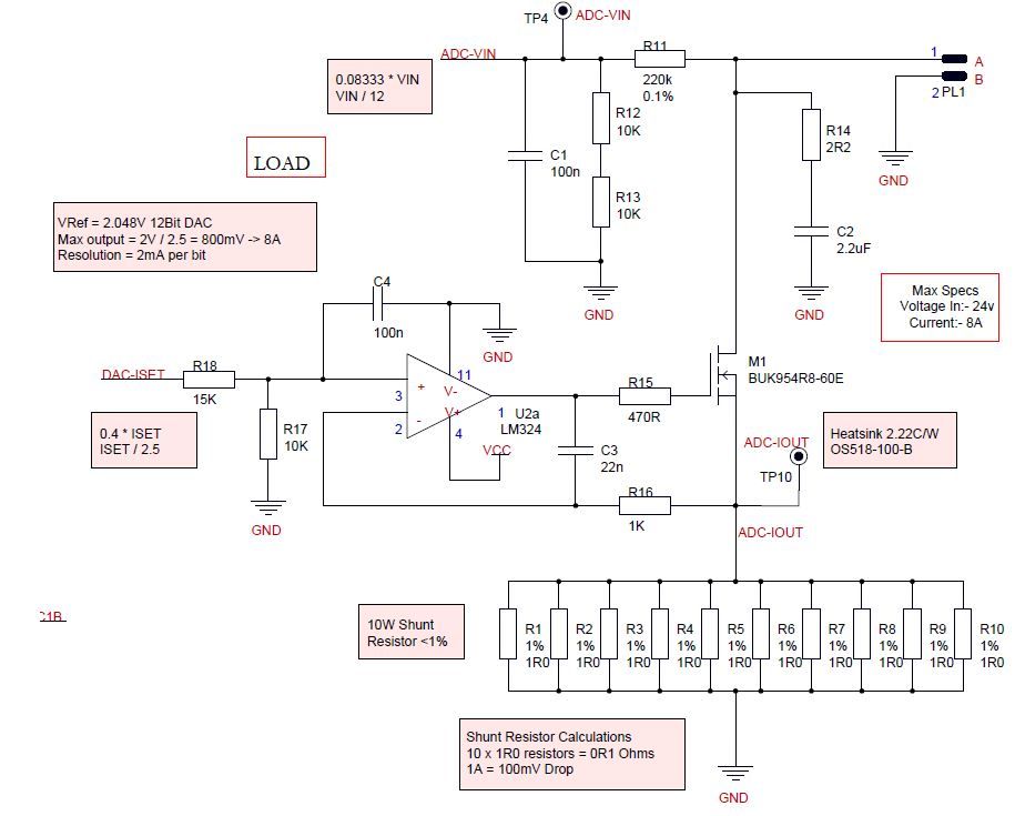
Before we get onto the op-amps we need to cover one more aspect of the circuit and that is those 10 resistors next to each other R1 – R10. They are 10 x 1 ohm resistors in parallel, parallel resistance can be a little confusing to calculate the total resistance of that section, however, considering they are all the same value we can cheat a little, we can divide the value of 1 resistor by how many are there, in this case, it is 1 divided by 10, or 0.1 ohms, If you where to put a multimeter across those resistors it would read 0.1 ohms, this is known as the sense resistor. Why 10? why not just 1 0.1 ohm resistor? Well for three reasons.
- Accuracy
- Power Dissipation
- Cost
The reason we have improvement in accuracy is because that 10 resistors in parallel will tend to even each other out in their errors and end up with a more precise resistance value than if you used 1 x 0.1 ohm resistor. One thing we haven’t really looked at is power. As current passes through a resistor it drops voltage (drops pressure as it passes through a kink) this drop in voltage is known as power dissipation, power can be many things, in this case, its heat. Many things rely on heat off resistors, your kettle, bathroom heater, hair dryer, hot water service and the list goes on. In this case, its an unfortunate by-product. However, lets just do a few quick calculations on how to calculate just how much power is there. This load is capable of carrying 8 amps, lets first work out how much voltage we will drop across our sense resistor of 0.1 ohms,
V = I x R
= 8 x 0.1
= 0.8 volts
Now we know how much our voltage dropped we can work out our power dissipation
P = V x I
= 0.8 x 8
= 6.4 watts
Let me tell you, that’s quite a lot of power dissipated from one resistor! Which brings me to the other element, cost, one 0.1 ohm resistor with a 1% accuracy that can dissipate 6.4 watts is in the order of $7 – $10 just for one resistor where as 10 x 1 ohm resistors that can dissipate 1 watt each are $0.30 each.
The purpose of these sense resistors is it allows us to accurately measure the current in the circuit against a known resistance, no mater what, ohms law always applies, as we have shown, if there is 8 amps going through a resistance of 0.1 ohms, there will always be a voltage drop of 0.8v. Like wise, if we put 1 amp through the 0.1 ohm resistor we will get a 0.1v drop, always. Try it, put any value of current into the above formula and you will get a proportional voltage drop across those resistors. Remember this, we will see why that’s important in a little while.
OK, Op-Amp time! Op-Amps can be very complicated beasts and we are certainly not going to cover all aspects of the op-amp in this instructable. If you wanted to read a bit more into the op-amp then this is a very good tutorial to explain them in detail. For this project I have used an LM324 which is one chip that has 4 op-amps inside, the op-amp we are considering at the moment is shown in the image above as U2a – LM324a.
On most op amps there are 5 pins, a non inverting input (pin 3), an inverting input (pin 2), an output (pin 1) and a power supply (pins 4 and 11). One important property of the op-amp that we need to consider is that it will do everything it possibly can on the output to try and keep the inputs at the same voltage. The op-amp hates having a difference of voltage on the input. In fact this is very important to understanding the inverting and non-inverting amplifier circuits.
The dummy load makes use of this very useful feature of the op amp to control the MOSFET gate (the kink in the hose) so that it can keep the current to the level we set. How does it know what the current is? By reading the sense resistor. Let’s have a look at that for a minute, in the image above, the sense resistors are R1 to R10 in parallel, as we have described the sense resistor will drop a voltage that is proportional to the amount of current flowing through it, as the very next connection in the circuit is ground (or 0 volts) ohms law says that if we have 1 amp flowing through the sense resistors that they will drop 0.1 volts. That means, if we have 0.1 volts at the top of the sense resistors and 0 volts at the bottom then we must have 1 amp flowing!
We are finally getting to the fun part! Now, if you have a look at the circuit above, the top of these resistors feed back to the inverting input of the op-amp (It does go through a few other resistors and capacitors but please ignore them for now, we will talk about them in another step, trust me when I say, that 0.1 v will be fed back to the inverting input). You will also notice that the gate of the MOSFET (M1 – BUK954R8-60E) is connected to the output of the op-amp. Going back to what we said earlier, that the op-amp will do everything it can on its output to keep its inputs the same, so with that in mind, if we set a voltage of 0.1 volts on the non-inverting input of op-amp, it will do everything it can on its output to get 0.1 volts on the inverting input. So, it will put as much voltage as it has to on the gate of the MOSFET (opening the tap) to open it enough so that 1A flows. Likewise if we set 0.8 volts on the non-inverting input, it will do everything it can on the output to get 0.8 volts on the inverting input. That is how it works, what ever voltage you set, it will drive the MOSFET enough to get the same voltage on the other input. It’s as simple as that!
For more detail: Arduino Programmable Constant Current Power Resistance Dummy Load
- How does the dummy load control current?
It uses a MOSFET as a variable resistor controlled by an op-amp that adjusts resistance based on voltage feedback from sense resistors. - Why are there 10 resistors instead of one for the sense resistor?
Using 10 resistors improves accuracy by averaging errors, handles power dissipation better than a single resistor, and is more cost-effective. - What is the maximum input voltage for this load?
The maximum input load voltage is 24V. - Can this project be set to constant power mode?
Yes, the load can be set to draw a constant current, constant resistance, or constant power. - How is the current measured in the circuit?
Current is measured by sensing the voltage drop across the 0.1 ohm equivalent sense resistor formed by 10 parallel 1 ohm resistors. - What type of MOSFET is used in this design?
An N-type MOSFET (specifically the BUK954R8-60E) is used to control the current flow. - Does the microprocessor calculate the resistance directly?
No, the microprocessor is bypassed for speed; an op-amp handles the immediate feedback loop to adjust the MOSFET gate voltage. - What is the minimum load current draw specified?
The minimum load current draw is 15mA due to op-amp offset. - How much power can the sense resistor section dissipate?
The sense resistor section dissipates approximately 6.4 watts when 8 amps are flowing through it. - What formula is primarily used to explain the theory?
The project relies on Ohm's Law (V = I x R) and the Power formula (P = V x I).