Arduino ISP – LOG
So this Lazy Old Geek (LOG) has had a lot of trouble getting Arduino bootload on Atmega chips.
I couldn’t get either of these to work with Arduino UNO Rev3.
http://arduino.cc/en/Tutorial/ArduinoISP
http://letsmakerobots.com/node/35649
So I developed a couple that worked for me:
http://www.instructables.com/id/My-Arduino-Bootloader/
http://www.instructables.com/id/UNO-Bootloader-In-Circuit-Programmer-1/
Problem: Well, my second Instructable works good for Atmega328s in a socket, but I have a Seeeduino that uses a SMD Atmega. So I can’t bootload it with my ICPs. See picture.
Solution: What many people may not realize is most of these Arduino In Circuit programmers use the same pins that are on the ICSP connector or sometimes called ISP.
ICSP: In-Circuit Serial Programming
http://en.wikipedia.org/wiki/In-circuit_serial_programming
Basically, this is a way of programming a microcontroller PCB through a connector.
ISP: In System Programming
http://en.wikipedia.org/wiki/In-System_Programming
Basically, the same thing. I don’t know the difference. They seem to be used interchangeably.
Step 1: ISP Cable
So I took my UNO ICP schematic and converted it to ICSP connectors. This makes it easier to hook up, then connecting six jumpers to various header pins on the Arduinos. See schematic
Construction: There’s a couple of ways to do this. You could take 2 2×6 female headers and solder wires or you can take six female-female adapter jumpers like these.
http://www.ebay.com/itm/New-31cm-40-PCS-Rainbow-Color-Flat-for-Arduino-Jumper-Cable-Wire-2-54mm-1P-F-F-/330885863082?pt=LH_DefaultDomain_0&hash=item4d0a5596aa
I used the second method.
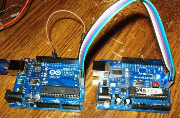
Two Arduinos with ICSP/ISP connectors
6 f-f adapters
1 m-m adapter
Identifying pin 1 on ICSP/ISP connectors. These connectors are 2×3 male headers. See picture. Sometimes pin 1 is identified by a dot or a 1 or if you turn the Arduino over, pin 1 is square instead of round pad.
What I like to do is make sure by using a DMM and check which pin is connected to ground. This is pin 6 of the connector and pin 1 is the opposite. See pinout drawing.
For future reference, I mark pin 1 with red nail polish.
Now you have pin 1 identified on the two Arduinos. Identify one as the source Arduino. Source is the Arduino used to bootload the other Arduino, the Target.
Take one of the f-f adaptors and connect 1 to 1 on the two Arduino ICSP/ISP connectors.
Take another and connect 2-2, 3-3, 4-4 and 6-6
Take another f-f and connect one end to pin 5 on the Target Arduino.
On the other end, connect the m-m adapter, plug the other end into D10 female header of the Source.
See picture and schematic.
Then I wrapped both connectors with transparent tape to keep them bundled in order.
And I marked each Pin 1 with red nail polish. See picture.
Step 2: LED Indicator
Optional:
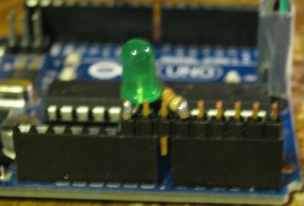
(I apologize for the fuzzy pictures)
Using just the ISP cable, it’s a little harder to tell if it bootloaded correctly or not. So I built an LED indicator for success.
I used a 9 pin male header, a 1.2K ohm resistor and a green LED.
One side of the resistor is connected to header pin for A0, the other side to the positive side of the LED.
The negative side of the LED is connected to Ground.
TIP: It doesn’t matter whether the resistor or the LED is connected to A0. It does matter if the LED is connected backwards or not. Also the resistor value is not to critical. A smaller value will mean a brighter LED.
Technically speaking you don’t really need nine pins but I like to have the header extended all the way to the end of the row so it’s harder to put it in the wrong holes.
Another thing I did is: notice one pin sticks out between the two female headers on the Arduino. I bent the bottom of that pin so that it couldn’t be inserted into the wrong header hole. See last picture.
For more detail: Arduino ISP – Lazy Old Geek (LOG)