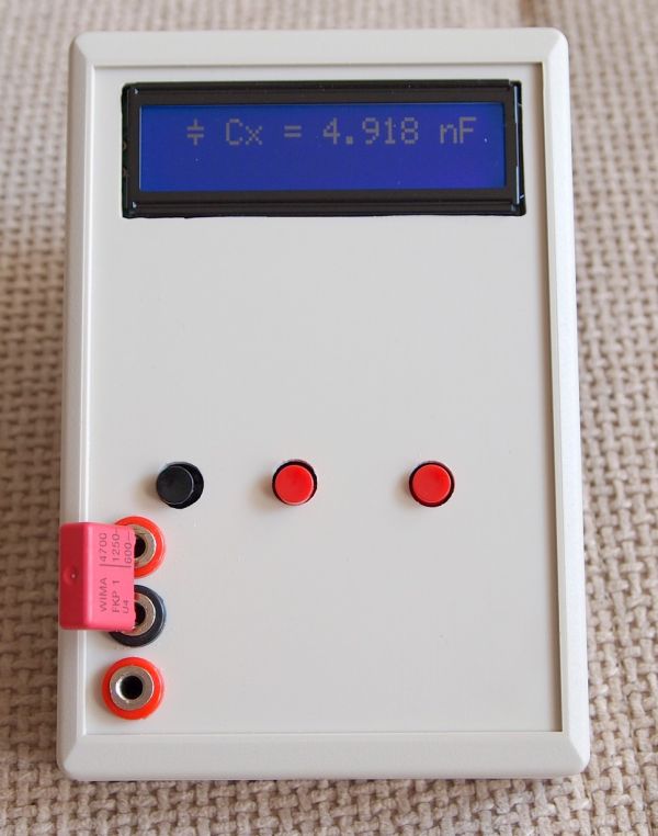
Summary of Advanced LC meter
This article details the construction of an advanced LC meter based on the LCM3 design, enabling measurements for capacitors (including electrolytic), inductors, and low resistances. The builder designed a custom PCB allowing top-mounted LCD display with a contrast trimmer and optional terminal connector. Key components include 1% metal film resistors, specific high-precision capacitors like styroflex and polypropylene types, and a low Rdc inductor. The device supports external power adapters to adjust backlight current.
Parts used in the Advanced LC Meter:
- LCD display
- Multiturn trimmer for contrast adjustment
- 3-pin terminal connector
- 1% metal film resistors
- Two 1nF 1% styroflex capacitors
- CX1 33nF polypropylene high voltage capacitor
- Low Rdc inductor
- Separate adapter connector
- R11 resistor for backlight current control
Description
After finishing my last project – “Simple LC meter“, there were some discussions in the forum I am a member of, that ability to measure electrolytic capacitors would be very useful in this type of device.
I searched the Web and found a very cute project named LCM3 on this Hungarian site: hobbielektronika.hu . I love Hungarian rock since my school days, but I don’t know a word in Hungarian 🙁 . So, I searched the Web again, this time for this specific project and found a Russian forum where the project was discussed in details and I got more useful information about parts, settings and so on.
Specifications of the LCM3 are (according to authors of the project):
Capacitors:
from 1pF to 1nF – resolution: 0.1pF, accuracy: 1%
from 1nF to 100nF – resolution: 1pF, accuracy: 1%
from 100nF to 1uF – resolution 1nF, accuracy: 2.5%
Electrolytic capacitors:
from 100nF to 100 000uF – resolution 1nF, accuracy: 5%
Inductance:
from 10nH to 20H – resolution 10nH, accuracy: 5%
Resistance:
from 1mOhm to 0.5Ohm – resolution 1mOhm, accuracy: 5%
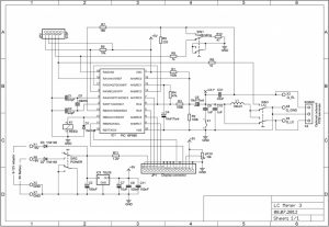
SCHEMATIC
PCB
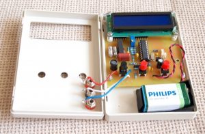
As usual I designed a new PCB. The PCB is designed in such a way, that it is possible to mount the LCD display on top of the board. The multiturn trimmer for adjusting the contrast is bellow the display, so it must be of this type : Тhere is also an option for mounting a 3-pin terminal connector, so it’s possible to use the whole device without an enclosure.
All resistors are 1% metal film. Two 1nF capacitors are 1% styroflex. CX1 – 33nF is also critical – this must be polypropylene high voltage capacitor. I tried with two types: 10% X2 275Vac and Panasonic 3% 800V – worked fine with both. The inductor must be with low Rdc. There is a connector for a separate adapter, which bypasses the ON/OFF button. Maybe on next revision of PCB I would add an onboard power connector. If the device is powered with external power adapter, you may increase back light current by decreasing the value of the resistor R11. You must consult with the datasheet of the display to select a proper value of the resistor.
PHOTOS
Source: Advanced LC meter
- What is the primary purpose of this project?
The project enables measuring electrolytic capacitors, which was identified as a useful addition after discussions about a previous simple LC meter. - How can I mount the LCD display on the PCB?
The PCB is designed to allow mounting the LCD display on top of the board. - Which type of capacitor must be used for CX1?
CX1 must be a 33nF polypropylene high voltage capacitor. - Can the device operate without an enclosure?
Yes, by mounting a 3-pin terminal connector, the whole device can be used without an enclosure. - How do I increase the backlight current when using an external power adapter?
You may increase the backlight current by decreasing the value of the resistor R11. - What kind of resistors are specified for the circuit?
All resistors in the project are specified as 1% metal film. - Does the inductor have specific requirements?
Yes, the inductor must have a low Rdc. - What is the resolution for measuring electrolytic capacitors between 100nF and 100000uF?
The resolution is 1nF with an accuracy of 5%.