
Summary of Adafruit 16 Channel PWM Servo Shield using Arduino Uno with Proteus Simulation
This Arduino project utilizes an Uno and an Adafruit 16-Channel PWM Servo Shield to control five RGB LEDs via I2C communication. Simulated in Proteus, the system employs the PCA9685 driver to generate smooth dimming and color transitions rather than simple on/off states. By allocating 15 of the shield's 16 channels for red, green, and blue components, the setup demonstrates efficient multi-channel PWM control suitable for educational embedded systems and DIY lighting prototypes.
Parts used in the Arduino RGB LED Project:
- Arduino Uno
- Adafruit 16 Channel PWM Servo Shield
- PCA9685 PWM controller
- 5 RGB LEDs
- I2C communication lines (SDA, SCL)
- Power connections
- Ground connections
Introduction
This Arduino RGB LED project uses an Arduino Uno with an Adafruit 16 Channel PWM Servo Shield in Proteus simulation to control 5 RGB LEDs with smooth lighting effects. It is a practical microcontroller project for learning PWM control in embedded systems and DIY electronics. Instead of simple ON and OFF output, the system creates soft dimming and color transitions. It also shows how a PWM shield can expand Arduino output control efficiently. This makes the project useful for students, hobbyists, and practical electronics learners.
How the Project Works
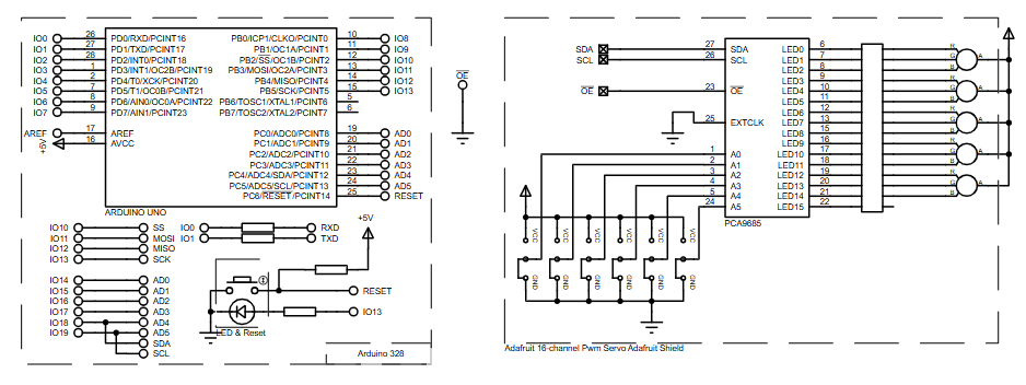
The project uses an Arduino Uno connected to an Adafruit 16 Channel PWM Servo Shield through the I2C lines, labeled SDA and SCL in the schematic. The shield is built around the PCA9685 PWM controller, which provides multiple PWM outputs for LED driving.
From the schematic, the PWM outputs are routed to 5 RGB LED groups, meaning each LED uses three control channels: red, green, and blue. That matches the total of 15 active PWM channels, which fits well within the 16-channel capability of the PCA9685.
The flowchart shows that the project starts by setting a PWM frequency of 100 Hz, defining minimum and maximum brightness values, and then running several LED dimming and RGB fading routines. First, the LEDs are initialized to a low-brightness state. Then the program cycles through individual LED fading and grouped RGB color transitions. The result is a smooth visual animation sequence in the Proteus simulation.
Workflow Explanation
1. Arduino Uno
The Arduino Uno acts as the main controller and sends commands to the PWM shield.
2. I2C Communication
The Uno communicates with the PWM shield using:
- SDA
- SCL
This reduces the number of pins needed compared to direct LED driving.
3. PCA9685 PWM Driver
The Adafruit shield uses the PCA9685 chip to generate accurate PWM signals for each LED channel. In the schematic, the outputs are labeled from LED0 to LED14, which are used for the RGB LED lines.
4. RGB LED Groups
There are 5 RGB LEDs, each requiring:
- 1 Red channel
- 1 Green channel
- 1 Blue channel
So the project uses:
- 5 × 3 = 15 PWM outputs
5. Animation Logic
According to the flowchart, the firmware:
- sets PWM frequency
- defines brightness limits
- fades individual LED channels
- performs RGB group dimming
- adds delays for visible transition effects
This creates a repeating RGB light animation pattern. The flowchart on page 1 shows setup values such as ledMIN = 50, ledMAX = 255, and repeated calls to dimLed and dimRgb routines across LED numbers and RGB groups.
Key Features
- Drives 5 RGB LEDs using a single PWM expansion shield
- Uses Arduino Uno as the main controller
- Communicates over I2C for cleaner wiring
- Uses the PCA9685 for multi-channel PWM generation
- Supports smooth LED dimming instead of simple ON/OFF switching
- Demonstrates grouped RGB color fading effects
- Ideal for Proteus simulation and visual electronics testing
- Good example of PWM-based lighting control in embedded systems
Components Used
Based on the provided schematic and description, the project uses:
- Arduino Uno
- Adafruit 16 Channel PWM Servo Shield
- PCA9685 PWM controller
- 5 RGB LEDs
- I2C communication lines (SDA, SCL)
- Power connections
- Ground connections
The schematic clearly shows the Arduino Uno connected to the shield through SDA/SCL, with PWM outputs from the PCA9685 going to the RGB LED lines.
Applications
This type of microcontroller project can be used in many practical areas, such as:
- Decorative RGB lighting systems
- LED animation demos for learning embedded systems
- Smart lighting prototypes
- DIY visual indicators
- Multi-channel PWM lighting control experiments
- Educational Proteus simulation projects
- Color effect generation in interactive electronics
- Arduino-based lighting controllers
Explanation of Code
No raw source code was included in your input, so the explanation below is based only on the provided description, schematic, and flowchart.
The firmware appears to be organized around PWM control functions for both single LED channels and grouped RGB channels.
PWM Initialization
The setup stage configures the PWM module with a frequency of 100 Hz. This frequency is suitable for visible LED brightness control and smooth dimming effects.
Brightness Limits
The flowchart defines:
- ledMIN = 50
- ledMAX = 255
These values are used as lower and upper brightness boundaries during fading operations.
Single LED Dimming
A function labeled dimLed is repeatedly called for LED channels from 0 to 14, which suggests channel-by-channel brightness control. The routine appears to dim LEDs up and down between the configured brightness limits.
RGB Group Dimming
Another routine, dimRgb, is used for RGB groups from 0 to 4. This indicates that each RGB LED is treated as one logical group, with separate red, green, and blue intensity ranges. Different minimum and maximum values are applied to produce varied color effects.
Delay and Animation Timing
The flowchart includes timing delays such as:
- 300 ms
- 100 ms
- 50 ms
These delays create visible transitions and help the lighting animation look smooth in the Proteus simulation.
Flowchart
Proteus Simulation
In the Proteus simulation, the Arduino Uno communicates with the Adafruit PWM shield and controls the RGB LEDs through the PCA9685 outputs. The visual behavior is an animated LED sequence where brightness changes gradually instead of abruptly. Based on the flowchart, the simulation begins with LED initialization, then performs channel dimming and RGB group fading with timed pauses between patterns. This makes the project useful for testing PWM-based color control before building it in hardware. The page 1 workflow specifically shows repeated dimming loops for LED channels and RGB groups, confirming that the simulated design is centered around PWM-based light animation.
Conclusion
This is a neat and practical Arduino Uno microcontroller project for learning how PWM-based RGB lighting works with the Adafruit 16 Channel PWM Servo Shield. Even with a simple concept, it teaches important ideas used in embedded systems, including I2C communication, LED dimming, grouped RGB control, and simulation-driven design. For students, hobbyists, and anyone exploring DIY electronics, it is a solid project for understanding how a Proteus simulation can turn a circuit diagram into a working visual demo.
Complete File
Adafruit 16 Channel PWM Servo Shield using Arduino Uno with Proteus Simulation
- How does the system achieve smooth lighting effects?
The system creates soft dimming and color transitions by using a PWM shield instead of simple ON and OFF output. - What chip provides multiple PWM outputs for LED driving?
The shield is built around the PCA9685 PWM controller which provides the necessary multiple PWM outputs. - Does the project use direct LED driving or I2C communication?
The Uno communicates with the PWM shield using I2C lines labeled SDA and SCL to reduce the number of pins needed. - How many active PWM channels are utilized for the 5 RGB LEDs?
The project uses 15 active PWM channels because each of the 5 LEDs requires three control channels for red, green, and blue. - What frequency is set for the PWM module during initialization?
The firmware sets a PWM frequency of 100 Hz which is suitable for visible LED brightness control. - Can this project be used for smart lighting prototypes?
Yes, this type of microcontroller project can be used for smart lighting prototypes and decorative RGB lighting systems. - What are the defined minimum and maximum brightness values?
The flowchart defines ledMIN as 50 and ledMAX as 255 to serve as brightness boundaries during fading operations. - Why is Proteus simulation useful for this design?
Proteus allows users to test PWM-based color control and visualize animated LED sequences before building the circuit in hardware.
