16×2 character LCD display is a very basic LCD module which is commonly used in electronic projects. 16×2 means it can display 2 rows of 16 characters (columns). Its other variants such as 16×1, 16×4 etc are also available. These LCDs are usually made using HD44870 compatible controllers. In this tutorial we will see how to interface a 16×2 Character LCD display with Arduino Uno development board. Arduino provides built in libraries for interfacing HD44870 compatible LCDs.
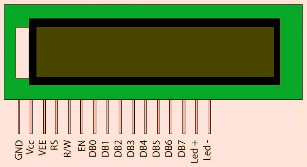
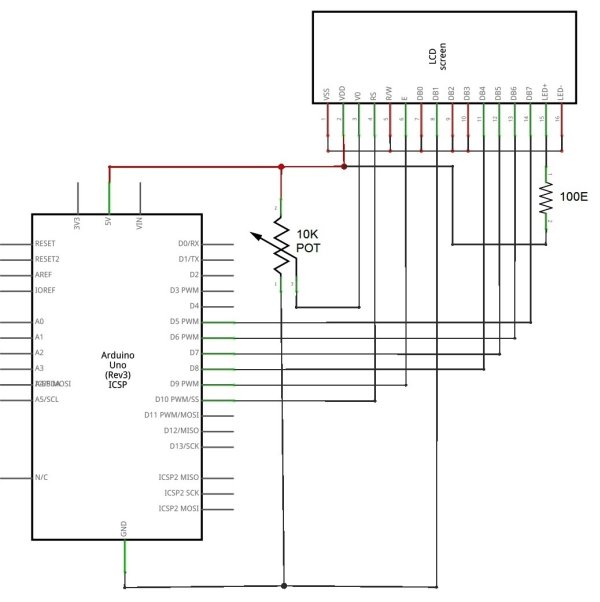
In a 16×2 character LCD display, there are 16 pins. First two pins VSS and VDD are for providing power to the display. Connect these pins to the GND and 5V supply pins in the Arduino Uno. 3rd pin of the LCD is named as Vo which is used for adjusting display contrast. We can use a 10KΩ preset for that, connect variable end to Vo and fixed ends to VSS and VDD. 4th pin RS is the Register Select pin which is used to multiplex the data and command information send to the LCD module. Data information is the ASCII value of the information to be displayed on the LCD and the command information will contain instructions such as the position in which the data is to be displayed etc. These two information will be multiplexed using pin RS and will send through DB0 – DB7 pins of LCD. If RS is high, then DB0 – DB7 will contain data information and when it is LOW then these lines will contain command information. 5th pin R/W is Read or Write pin which will determine whether the data is to be written or it is to be read from the LCD display. HIGH value of this pin will indicate the data is read from the display and LOW value indicates writing information to the display. Normally we need only writing values to the display, so we usually tie RW to GND. 6th pin E is the Enable pin of LCD. High value on E will indicate valid information on DB0 – DB7 pins. We can power the LCD’s back-light LED using last two pins.
The interface between this LCD and Arduino can be 8 bit or 4 bit and the difference between them is in how the data or commands are send to LCD. In the 8 bit mode, 8 bit data and commands are send through the data lines DB0 – DB7 and data strobe is given through E input of the LCD. But 4 bit mode uses only 4 data lines. In this 8 bit data and commands are splitted into 2 parts (4 bits each) and are sent sequentially through data lines DB4 – DB7 with its own data strobe through E input. The idea of 4 bit communication is introduced to save pins of the controller. You may think that 4 bit mode will be slower than 8 bit. But the speed difference is only minimal. As LCDs are slow speed devices, the tiny speed difference between these modes is not significant. Just remember that Arduino Uno is operating at high speed in the range of 16MHz and we are viewing LCD with our eyes. Due to Persistence of Vision of our eyes we will not even feel the speed difference.
Arduino LiquidCrystal Library
Arduino LiquidCrystal library enables us to interface LCDs having Hitachi HD44780 or compatible controllers with Arduino Boards. This library can work either in 8-bit or 4-bit mode depending upon how we initialize LCD connections.
LiquidCrystal()
This function is used to initialize connections of LCDs. It creates a variable of type LiquidCrystal. By proper initialization of connections, we can control LCD either in 8-bit or 4-bit mode.
Syntax :
LiquidCrystal(RS, EN, D4, D5, D6, D7)                      // 4-bit mode
LiquidCrystal(RS, RW, EN, D4, D5, D6, D7)                  // 4-bit mode
LiquidCrystal(RS, EN, D0, D1, D2, D3, D4, D5, D6, D7)      // 8-bit mode
LiquidCrystal(RS, RW, EN, D0, D1, D2, D3, D4, D5, D6, D7)  // 8-bit mode
Description
- RS indicates the Arduino pin number to which LCD RS (Register Select) is connected.
- EN indicates the Arduino pin number to which LCD EN (Enable) is connected.
- RW indicates the Arduino pin number to which LCD RW (Read / Write) is connected
- D0 – D8 indicates Arduino pin numbers to which LCD data pins are connected.
Note 1 : D0 – D3 pins are optional, if omitted the LCD will be controlled in 4-bit mode.
Note 2 : RW pin is also optional. RW pin is used to indicate Read or Write operation is to be performed. Since LCD is an output device, we usually write data to it, so RW pin can be tied to ground instead of connecting it to Arduino.
Example :
LiquidCrystal lcd(12, 11, 10, 5, 4, 3, 2);
Where lcd is the variable.
begin()
This function initializes the interface to LCD display and it also sets the size (columns and rows) of the display. It should be called before any other LCD library functions. The parameters of this function will be the dimensions of the display, that is the number of rows and columns.
For more detail: Interfacing LCD with Arduino Uno