Introduction
Remote control cars have been used for ages just like boy’s toys or gadgets that make people enjoy the feeling of driving from the comfort of their homes. As children’s toys radio-controlled Cars still play an informative role for all those willing to learn about electronics, programs, and mechanics. This project brings the notion of the conventional radio control car into contemporary society through computing and wireless technology. Specifically, the team of students set out to create a scaled vehicle that could be driven from anywhere using a smartphone app connected through the Internet of Things.

By incorporating an Arduino board with built-in WiFi and cloud services, their design paved the way for new possibilities in remote vehicle control. In this in-depth commentary, I will explore how the team brought their vision to life. From identifying the technical challenges to devising innovative solutions, their journey provides valuable insights for others embarking on ambitious hands-on learning projects.
Hardware Design
Selection of Components
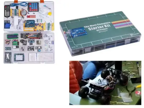
As the backbone of their design, the team wisely chose the Arduino UNO R4 as it integrated the required processing power and onboard WiFi connectivity. For precise motor control, an H-bridge motor driver was employed to independently drive the two DC motors. A stepper motor offered accurate steering rotations. Other key components included batteries, sensors, and indicator LEDs. Careful selection of components upfront streamlined development.

Power System Design
To power the electronics and propel the vehicle, 7.4V batteries were tapped. Wiring harnessed power to the motor driver and Arduino board. The motor driver’s voltage regulator circuit safely supplied 5V to the microcontroller. Separate battery leads energized the indicator lights efficiently. Proper power routing minimized interference and ensured components received adequate current.
Motor Control Circuitry
Developing a robust motor control scheme required interfacing the motor driver, Arduino, and DC/stepper motors properly. PWM and direction pins from the Arduino were mapped to the H-bridges motor input channels. Pulse widths modulated the motor speeds while input logic controlled movement directions. The stepper motor also connected to the driver which facilitated programmatic rotation increments. Testing verified smooth, calibrated responses from the electrical design.
Mechanical Integration
Through clever mechanical CAD modeling and 3D printing, all electronics and mechanicals interfaced seamlessly within a protected yet customizable chassis. Motors affixed to low-friction bearings for precision rotations. A headlight bracket precision-mounted indicator LEDs. Careful fabrication ensured components remained supported and accessible for testing iterations. Well-integrated hardware served as the foundation for remote functionality.
Sensor Integration
Additional sensors augmented the vehicle’s intelligence and utility. A photoresistor triggered automatic headlights in low light. However, proximity sensors conflicted with infrared signals, necessitating removal. Instead, the team innovated indication LEDs to creatively signal turns and reverse via coded patterns, adding safety without interfering with sensors. Thoughtful sensor selection enriched functionality.
Software Design
Control Algorithm Development
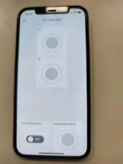
To enact remote commands, control algorithms transformed joystick positions and button presses into motor control signals. Pulse widths modulated the motors proportionally to joystick displacement for natural acceleration and braking. Time delays between commands prevented abrupt, potentially unsafe movements. Servos automatically recentered the steering to straight positions. Testing iteratively calibrated control gain and response times for realistic driving dynamics.
Integration with Cloud Platform
Leveraging the Arduino Cloud API, code uplinked control signals from the mobile app to the microcontroller via Internet connectivity. Parsing incoming data packets, the Arduino interpreted commands and updated motor control variables accordingly. However, inherent latency required buffering real-time inputs to avoid instability from lagged responses. Careful coding compensated for transmission delays, smoothing the cloud-centric experience.
Indicator Light Programming
Additional code implemented automatic headlights through photoresistor readings. Pulsing indicator LED patterns creatively signaled turns and reverses without interfering with sensors. Conditional logic activated lights proportionally to movement directions discernible even at a distance. Subtle enhancements enriched the driving realism.
Manufacturing and Assembly Planning
Project Scheduling
To coordinate concurrent engineering tasks, the team developed a thorough Gantt chart outlining discrete work packages. Individuals took ownership of hardware prototyping, coding modules, manufacturing planning, budgeting/sourcing, and testing/integration phases. Breaking the large project into focused workstreams allowed parallel progress and early identification of interdependencies.
Rapid Prototyping Techniques
Efficient production centered on rapid 3D printing and iterative assembly/testing cycles. Repeated morphological evaluations informed minor model revisions while conserving resources. Sourcing electronic components in bulk reduced costs versus single orders. Just-in-time manufacturing and flexible project scheduling facilitated multiple design iterations.
Quality Assurance Processes
Comprehensive testing procedures validated all function and performance specifications. Checklists screened for electrical, mechanical, and software defects. Control mapping, response times, and wireless connectivity underwent rigorous evaluations. Debugging isolated issues for permanent resolutions. Formal documentation and sign-offs certified the vehicle met objectives before completion. Rigorous QA/QC ensured the delivery of a robust prototype.
Addressing Challenges
Troubleshooting Motor Issues
They were resolving drive motor faults required carefully examining all potential failure points. Methodically checking connections uncovered a loose wire – a simple yet elusive problem. Confirming solid contacts prevented recurrence. Persistence in root cause analysis aided swift resolution.
Overcoming Connectivity Hurdles
Initial WiFi configuration posed challenges. Evaluating packet sizes, encryption protocols, and transmission schedules optimized data throughput. Returning antennas boosted wireless signal strength for longer ranges. Perseverance in optimizing wireless parameters resulted in reliable cloud communications.
Adapting to Sensor Interference
When proximity sensors interfered with infrared signals, rather than persist with a flawed design, the team innovated alternative solutions. Removing problematic components showed flexibility. Creative LED-based signaling expanded functionality without causing issues. Agility in modifying plans circumvented setbacks.
Conclusion
Through diligent teamwork and engineering resourcefulness, the students accomplished their goal of creating an internet-connected radio-controlled vehicle prototype. Their concurrent engineering approach allowed timely progress across specialized workstreams. Rigorous testing and refining continuously improved design iterations.
Challenges provided valuable learning by strengthening debugging skills, systems thinking, and adaptive problem-solving aptitudes. While not commercially polished, the proof-of-concept demonstrated new interfaces between physical computing and online connectivity. Overall, the project showcased the development of technical abilities alongside beneficial “soft” project management techniques serving students well in future careers. Their innovative design reflects the blending of established technologies with creativity to push boundaries.
CODE
// Code generated by Arduino IoT Cloud, DO NOT EDIT.

#include <ArduinoIoTCloud.h>
#include <Arduino_ConnectionHandler.h>

const char DEVICE_LOGIN_NAME[] = "b3b27576-b1b5-47d5-afbb-7ddd51853ab2";

const char SSID[] = SECRET_SSID; // Network SSID (name)
const char PASS[] = SECRET_OPTIONAL_PASS; // Network password (use for WPA, or use as key for WEP)
const char DEVICE_KEY[] = SECRET_DEVICE_KEY; // Secret device password

void onAvantiChange();
void onAvantiIndietroChange();
void onAvDestraChange();
void onAvSinistraChange();
void onIndietroChange();

bool avanti;
bool avantiIndietro;
bool avDestra;
bool avSinistra;
bool indietro;

void initProperties(){

ArduinoCloud.setBoardId(DEVICE_LOGIN_NAME);
ArduinoCloud.setSecretDeviceKey(DEVICE_KEY);
ArduinoCloud.addProperty(avanti, READWRITE, ON_CHANGE, onAvantiChange);
ArduinoCloud.addProperty(avantiIndietro, READWRITE, ON_CHANGE, onAvantiIndietroChange);
ArduinoCloud.addProperty(avDestra, READWRITE, ON_CHANGE, onAvDestraChange);
ArduinoCloud.addProperty(avSinistra, READWRITE, ON_CHANGE, onAvSinistraChange);
ArduinoCloud.addProperty(indietro, READWRITE, ON_CHANGE, onIndietroChange);

}

WiFiConnectionHandler ArduinoIoTPreferredConnection(SSID, PASS);