
Summary of Building your own CNC router/milling machine
The author, an Industrial Design student, details the design and construction of a custom CNC milling machine using SolidWorks CAD software. Emphasizing rigidity and maintenance, the build features an aluminum frame with accessible guiderails and separate bearing blocks to ensure longevity and ease of cleaning. The project integrates manual machining skills with modern design tools to create a functional home workshop machine.
Parts used in the Custom CNC Milling Machine:
- Dremel tool
- Drawer slides
- Pieces of wood
- SolidWorks CAD modeling tool
- Manual lathe
- Manual milling machine
- Maytec 40x80mm profiles
- 10 mm thick aluminium endplates
- Corner pieces
- Square structural piece
- Milled aluminium blocks
- Dust covers
- Angular profile
- Brass milled t-nuts
- 2mm aluminium plates
Already at the age of 12 I was dreaming of making a machine which could make things! A machine which would give me the opportunity to create products for in and around the house. Two years later I stumbled ont the words ‘Computer Numerical Control’ or more specifically the CNC milling machine. After I found out people were able to build one themselves in their own shed, I knew it! I had to build one, I yearned to have it!!
For three months I tried to find the proper parts (A dremeltool, drawer slides, pieces of wood, etc.), but I didn’t really know how to build a CNC. The idea fell into oblivion.
In August 2013 the idea to build a CNC milling machine captivated me again. I just finished the first year of my bachelor in Industrial Design, so I was confident enough to start a build. The real difference between now and 5 years ago was, I learned to work with metal on manual milling machines and lathes and above all I had the right tools to design a machine.
This Instructable will show you how I built my CNC milling machine. I know a lot of CNC dreamers do not have the knowledge or tools to build a full metal machine. I still think and hope this Instructable inspires you to make your own machine. I include all of the necessary steps I went through in designing and building this CNC milling machine. All of the drawings I used to build my machine will be available.
Step 1: The Design and CAD model
It all started with a proper design, in my case a few sketches to get a good feeling for the dimensions and shape. Quickly after the sketching phase came the CAD model. I created my model in SolidWorks. If you plan to design your own machine I recommend a parametric CAD-modeling tool. Your machine will most likely have a lot of parts which have to fit together neatly, sometimes with some strange dimensions (for example pre-ordered parts). After all the parts were modeled, technical drawings were made. I used these drawings to machine all of the custom parts on the manual lathe and milling machine.
Since I’m a lover of good designed tools, I tried to make maintenance and the possibility to adjust things on the machine as easy as possible. Bearings could have been integrated in the machine, but I chose to place them in separate bearing blocks (in case it needs to be replaced in the future). Keeping your machine clean is very important too, so guiderails are all accessible (in case of the x-axis by detaching some cover plates)
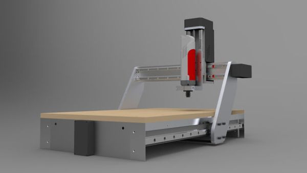
De drawing above gives an overview of the main mechanical parts I will cover in this Instructable. I will of course also cover the electrical part of the machine. A PDF with the main dimensions is also attached.
Step 2: The frame
The frame provides the machine a rigid basis, not only to place it in your workshop but also for working on. To the frame the gantry will be mounted on sliding rails and later on a work surface. It also houses the stepper motor and spindle for the x-axis. I constructed my frame from 2 Maytec 40x80mm profiles, 2 endplates (both 10 mm thick aluminium), 4 corner pieces and a square structural piece.
All of the profiles are sawed right-angled and afterward milled exactly square. With the corner pieces a heavy (well relatively lightweight; it’s all aluminium) frame was bolted together. The square frame made from the smaller profiles were mounted with 4 milled blocks (aluminium) on the inside of the Maytec profiles.
Since the frame sits beneath the worksurface dust could fall down on the guiderails (you want to keep them clean, more about that in step 5). To prevent this, dust covers were made and mounted around the guiderails. A angular profile mounted with brass milled t-nuts onto the may tech frame and 2mm aluminium plates mounted in the milled pockets on the endplates.
For more detail: Building your own CNC router/milling machine
- Why did the author decide to build a CNC milling machine?
The author dreamed of making a machine to create products for the house after learning about Computer Numerical Control and discovering that people could build one themselves. - What software was used to design the machine?
The author created the model in SolidWorks and recommends using a parametric CAD-modeling tool for complex parts. - How were custom parts manufactured?
Technical drawings made from the CAD model were used to machine all custom parts on a manual lathe and milling machine. - Why were bearings placed in separate blocks instead of being integrated?
Separate bearing blocks were chosen to make future replacements easier if maintenance is needed. - What material was used to construct the machine frame?
The frame was constructed from Maytec 40x80mm profiles, 10 mm thick aluminium endplates, corner pieces, and a square structural piece. - How does the design protect the guiderails from dust?
Dust covers were mounted around the guiderails using an angular profile and brass milled t-nuts to prevent debris from falling on them. - Can the guiderails be cleaned easily?
Yes, the guiderails are designed to be accessible, such as by detaching cover plates on the x-axis. - What is the primary function of the frame?
The frame provides a rigid basis for mounting the gantry, work surface, stepper motor, and spindle while supporting the machine in a workshop.