
Summary of PWM Control using Arduino – Learn to Control DC Motor Speed and LED Brightness
This article explains PWM control using Arduino, a high-efficiency method for regulating power to loads like LEDs and DC motors. It defines PWM as a high-frequency square wave where varying the duty cycle adjusts output power. The tutorial covers two practical applications: controlling LED brightness and adjusting DC motor speed by modifying the ON/OFF time ratio of the signal.
Parts used in the PWM Control Project:
- Arduino board
- LED
- DC motor
- PWM controller
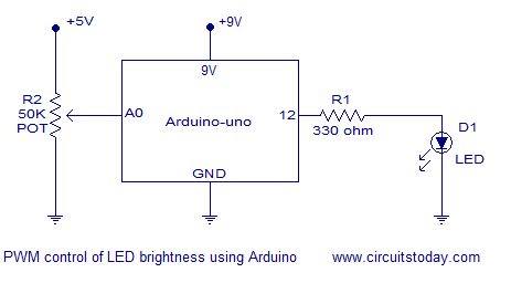
In this article we explain how to do PWM (Pulse Width Modulation) control using arduino. If you are new to electronics, we have a detailed article explaining pulse width modulation. We have explained PWM in this tutorial using 2 examples which will help you learn how to control LED brightness using PWM and how to control DC motor speed using PWM.
PWM control using arduino.
PWM control is a very commonly used method for controlling the power across loads. This method is very easy to implement and has high efficiency. PWM signal is essentially a high frequency square wave ( typically greater than 1KHz). The duty cycle of this square wave is varied in order to vary the power supplied to the load. Duty cycle is usually stated in percentage and it can be expressed using the equation : % Duty cycle = (TON/(TON + TOFF)) *100. Where TON is the time for which the square wave is high and TOFF is the time for which the square wave is low.When duty cycle is increased the power dropped across the load increases and when duty cycle is reduced, power across the load decreases. The block diagram of a typical PWM power controller scheme is shown below.
Control signal is what we give to the PWM controller as the input. It might be an analog or digital signal according to the design of the PWM controller. The control signal contains information on how much power has to be applied to the load. The PWM controller accepts the control signal and adjusts the duty cycle of the PWM signal according to the requirements. PWM waves with various duty cycle are shown in the figure below.
In the above wave forms you can see that the frequency is same but ON time and OFF time are different.Two applications of PWM control using arduino is shown here. Controlling the LED brightness using arduino and motor speed control using arduino.
For more detail: PWM Control using Arduino – Learn to Control DC Motor Speed and LED Brightness
- What is PWM control?
PWM stands for Pulse Width Modulation, a method for controlling power across loads using a high frequency square wave. - How does duty cycle affect power?
Increasing the duty cycle increases power dropped across the load, while reducing it decreases the power. - What is the typical frequency of a PWM signal?
A PWM signal is typically a high frequency square wave greater than 1KHz. - Can I use PWM to control LED brightness?
Yes, the article demonstrates controlling LED brightness using PWM with an Arduino. - Can I use PWM to control DC motor speed?
Yes, the article provides an example of controlling DC motor speed using PWM with an Arduino. - How is duty cycle expressed?
Duty cycle is usually stated in percentage and calculated using the equation % Duty cycle = (TON/(TON + TOFF)) *100. - What is the role of the control signal?
The control signal contains information on how much power has to be applied to the load and tells the controller what duty cycle to adjust.