Summary of Arduino Chessclock
This article details the construction of a custom Arduino-based chess clock. The project involves designing a circuit with multiplexed 7-segment displays, programming a countdown timer with reset and calibration features, and assembling the hardware using a PCB or breadboard. The author emphasizes prototyping on a breadboard first to verify connections before final assembly.
Parts used in the Arduino Chess Clock:
- Arduino nano (or any arduino UNO type)
- Soldering iron
- Solder
- PCB board or vero board
- 2 dual AA battery holders
- 3 X 10k OHM resistors
- Fuse holder
- 2 X earth pins from 2 UK plugs
- 2 X 4 digit 7-segment displays
- Buzzer
- 1 toggle switch
- 1 button small (press to make type)
- USB 1 cable
- Mics fittings and nuts bolts
- Casing (optional)
- Breadboard and jumper cables
I could not find instructions on a good Arduino chess clock so instead I built my own which I will describe here.
Step 1: Parts list
here are the things you will need:
Arduino nano (or any arduino UNO type will do)
soldering iron
solder
PCB board or vero board
2 dual AA battery holders
3 X 10k OHM resistors
fuse holder
2 X earth pins from 2 UK plugs
2 X 4 digit 7-segment displays
buzzer
1 toggle switch
1 button small (press to make type)
USB 1 cable (or whatever fits in your Arduino)
mics fittings and nuts bolts. For this I bid and won a meccano set on ebay and used what I found
Casing (optional)
breadboard and jumper cables (optional but recommended to prototype it first)
time, plenty of time!
I attached an image but this was from my spares after my build so some components are missing as noted.
Step 2: Prototyping
The whole project can be split into these parts:
1. getting the circuit right
2. the program
3. the physical layout
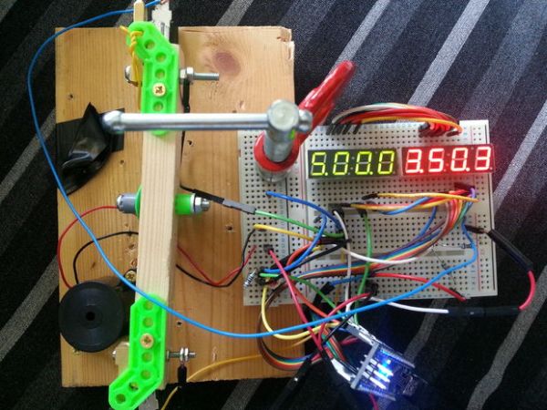
This step is optional since I will give you the circuit diagram but I do highly recommend that you give it a go in a breadboard first as it will confirm (or not) that you have all the parts that you need and enable you to think about the physical layout of all the pieces for a housing or base.
I have attached here a picture of my prototype in a breadboard and also a circuit diagram. Some notes on the circuit:
1. In the top left of the circuit diagram shows the pin on the display that is connected to the segment (Cathodes) or the digit (Anodes).
2. You will note that for each display the segments (Cathodes) are connected to the respective segment on the other display. This is because the display is multiplexed to display the correct digits
3. the reset switch and the rocker is wired up with pull down resistors so as to keep the input LOW when the respective button is not depressed. see http://www.arduino.cc/en/tutorial/button for more details on this.
4.The power circuit is completely separate but simple. It is 4 AA batteries in serial with a switch are soldered into the red and black leads of to a cut USB cable. The USB cable then goes into the arduino.
Step 3: The program
Once you have it on a breadboard then you need to write the controller. Fortunately for you I have attached my code here but I would encourage you to have a go or tweak this code. If you are going to write it from scratch you first work out which pins to set to what to make all the 10 digits, I have then coded an additional 2 patterns, one for when time is run out and one to represent 10 in a single digit (see image).
The next step is to multiplex the digits so you can potentially display a different number or pattern on each of the 8 digits. I tweaked the speed of the multiplexing until it looked right, too fast and the numbers merge between neighboring digits and too slow and the naked eye can notice the multiplexing.
The next step is to count the numbers down as 2 sets of 4 numbers representing 2 countdowns. I chose to use the first digit for minutes, the next 2 for seconds and the last one for tenths of seconds but you could chose to have 2 for minutes and 2 for seconds.
The countdown can be calibrated with a simple for loop that does nothing so that a tick of a ‘second’ on the display is actually a real second. I got mine pretty close but I figured that it doesn’t matter too much for an informal game of chess if each play has the same number of units. I guess you might want to make it more accurate if you want to use your chess clock for a tournament or even to time an egg!
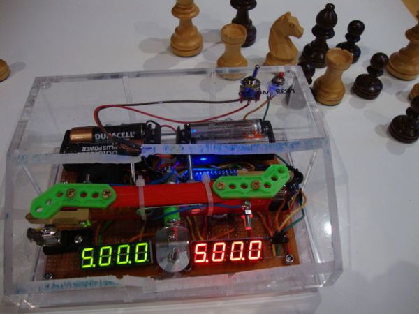
The clock loads into reset mode when turned on. Then it waits for the rockers to be hit on either side and counts down from the (default) 5 mins. The code listens to the reset button when the rocker is balanced. if it is hit then the clock goes into reset mode again. At this point the reset button can be used to cycle through the minutes desired for each play from 1 to 10. when the desired time is displayed the rocker can be hit again to start the clock.
lastly you need it to do something to indicate that the time has run out in my case it displays all dashes (-) and plays a series of beeps, then it shows one side as 0000 (the loser) and the other side as whatever time was unused by the winner.
For more detail: Arduino Chessclock
- What components are required for the major parts of this project?
The project requires an Arduino nano, soldering iron, solder, PCB board, two dual AA battery holders, three 10k ohm resistors, a fuse holder, two earth pins, two 4-digit 7-segment displays, a buzzer, a toggle switch, a small button, a USB cable, and mechanical fittings. - How should the circuit be tested before final assembly?
You should prototype the entire project on a breadboard first to confirm you have all necessary parts and to plan the physical layout for the housing. - Why are the segments connected across both displays?
The segments are connected because the display is multiplexed to correctly show digits on both units simultaneously. - How is the power circuit configured?
The power circuit uses four AA batteries in series connected via a switch to the red and black leads of a cut USB cable which plugs into the Arduino. - How does the program handle the countdown timing?
The code counts down as two sets of four numbers representing minutes, seconds, and tenths of seconds, calibrated using a simple for loop to ensure accuracy. - What happens when the time runs out?
The display shows all dashes and plays a series of beeps, then indicates the loser with 0000 and the winner with their unused time. - Can the default time settings be changed?
Yes, pressing the reset button while the rocker is balanced allows cycling through desired play times from 1 to 10 minutes. - Is a casing mandatory for this build?
No, a casing is listed as optional, though using one helps secure the physical layout of the pieces.