
Summary of How to make your own Arduino board
This article guides readers through building a custom Arduino board on a perfboard to save costs and gain design flexibility. It highlights advantages like lower component costs ($15 vs $30), direct chip usage for projects, and easier shield creation. The guide details the assembly process, including installing an IC socket, wiring voltage regulators (5V and 3.3V), and connecting power components. It notes that programming requires a breakout board or existing Uno clone due to the difficulty of integrating the USB-to-Serial adapter directly onto the perfboard.
Parts used in the Custom Arduino Board:
- perfboard
- two 10 uf electrolytic capacitors
- two 10 uf tantalum capacitors
- 7805 voltage regulator (5v)
- LM1117T-3.3 voltage regulator(3.3v)
- green LED
- red LED
- two 150 ohm resistors
- 10k resistor
- one 0.1 uf capacitor (ceramic disk)
- two 22 pf capacitors (ceramic disk)
- 16 MHz crystal oscillator
- momentary push button switch
- jumper wires
- female headers (three rows of eight)
- row of 6 male headers
- female wall wart power jack
- ATmega328 with bootloader
- 28 pin DIP IC socket
If your are like me which I am guessing you are, then ever since you got into doing stuff with arduino you have wanted to make your own arduino board. You may be surprised to find out that making the prototyping board is actually very easy, and can have several advantages over using the commercially sold board. For one thing, All the components together cost a little over 15 US dollars as opposed to the $30 that the Uno board sells for. second, you may not actually want a board, but may simply want the atmega chip as the heart of the project, like if you are making a synthesizer or even a robot. In that case, you can just attach the hardware necessary to use the chip, and solder to the pins you need to use without needing the board. Another advantage is making shields. You have probably noticed that digital pins 7 and 8 are not the standard distance apart, which makes it difficult to make your own custom shields without paying the $15 dollars for a protoshield every time you make one. But if you make your own board on perfboard, the headers will be the standard distance apart and you can make your own shields with ease. Also, you may need to permanently add the board to your project, and for that you may not want to use the more expensive arduino boards. This board however is half the price, and easy to add to custom projects.
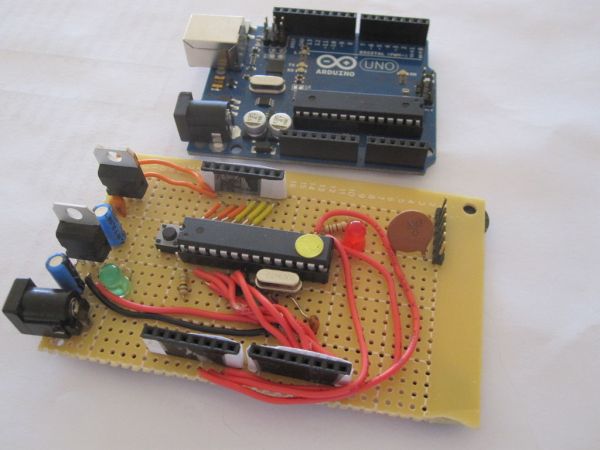
The only down side is that some parts of the arduino are kind of hard to build on perfboard. Most notably the Serial to usb adapter chip, which allows the microcontroller to interface with the computer through usb. You could use a good old RS232 jack, but they are not on a lot of newer computers. So to program your homemade board you will either need a break out board which does have the chip (get one here: http://www.jameco.com/webapp/wcs/stores/servlet/Product_10001_10001_2117341_-1), or an arduino Uno or clone board to program the chip ( I used the former.)
Either way it is a fun and informative project.
Step 1: Materials
otherwise here is the parts list:
-perfboard
-two 10 uf electrolytic capacitors
-two 10 uf tantalum capacitors
-7805 voltage regulator (5v)
-LM1117T-3.3 voltage regulator(3.3v)
-green LED
-red LED
-two 150 ohm resistors
-10k resistor
-one 0.1 uf capacitor (ceramic disk)
-two 22 pf capacitors (ceramic disk)
-16 MHz crystal oscillator
-momentary push button switch
-jumper wires
-female headers (I used three rows of eight)
-row of 6 male headers
-female wall wart power jack
-ATmega328 with bootloader
-28 pin DIP IC socket
Step 2: Install the socket
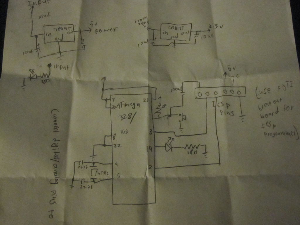
The first step is after finding a good sized perfboard is to find a good place for the chip, and place the IC socket where you want it paying attention to the notch witch will be matched with the notch on the chip. also find where you want your power jack. You should place it on the edge of the board probably in the corner. I widened the holes on the board with a 1/16 inch drill bit, but still had to fold the leads on the jack using needle nosed pliers to get it to fit through. On the jack, the pin on the back connecting to the post on the inside is positive, and the one on the bottom connected to the metal on the inside is ground (the pin on the side is not needed. You could solder it for extra support, but I just broke it off). Remember this when connecting the regulators.
Step 3: Adding the 5v regulator
Now it is time to add the five volt regulator. This is technically the only regulator you need to power the chip, but if you want a 3.3v pin (some breakout boards or sensors require 3.3v so the pin is nice to have), you will need to add the 3.3v regulator. These regulators require two decoupling capacitors each. Holding the 7805 printed side facing you, and the pins pointing down, the one furthest left is the input, the center is ground and the furthest right is the output. connect one 10 uf electrolytic capacitor to between the output and ground and the input and ground, being sure to connect the smaller leg to ground. connect the positive from the power jack to the furthest input pin, and ground from the power jack to the center pin.
-two 10 uf electrolytic capacitors
-two 10 uf tantalum capacitors
-7805 voltage regulator (5v)
-LM1117T-3.3 voltage regulator(3.3v)
-green LED
-red LED
-two 150 ohm resistors
-10k resistor
-one 0.1 uf capacitor (ceramic disk)
-two 22 pf capacitors (ceramic disk)
-16 MHz crystal oscillator
-momentary push button switch
-jumper wires
-female headers (I used three rows of eight)
-row of 6 male headers
-female wall wart power jack
-ATmega328 with bootloader
-28 pin DIP IC socket
For more detail: How to make your own Arduino board
- How much does it cost to make your own Arduino board compared to buying one?
All components together cost a little over 15 US dollars as opposed to the $30 that the Uno board sells for. - Can I use this method if I just want the ATmega chip without a full board?
You can attach the hardware necessary to use the chip and solder to the pins you need to use without needing the board. - What is the main advantage of making your own board regarding shields?
If you make your own board on perfboard, the headers will be the standard distance apart and you can make your own shields with ease. - Why is the Serial to usb adapter chip hard to build on perfboard?
The article states that some parts of the arduino are kind of hard to build on perfboard, most notably the Serial to usb adapter chip. - How do I program my homemade board if I cannot build the USB adapter myself?
You will either need a break out board which has the chip or an arduino Uno or clone board to program the chip. - Which voltage regulators are required for the project?
The project uses a 7805 voltage regulator for 5v and an LM1117T-3.3 voltage regulator for 3.3v. - How should the 7805 voltage regulator be oriented when soldering?
Holding the 7805 printed side facing you with pins pointing down, the left pin is input, center is ground, and right is output. - What type of power jack is specified for this project?
The parts list specifies a female wall wart power jack.
