
Summary of Program ESP8266 With NodeMCU
Summary: This guide shows how to program an ESP12F using a NodeMCU board (using its CP2102 USB‑to‑UART) as an easy programmer. It covers preparing a custom NodeMCU programmer PCB, wiring a minimal ESP12F breakout (3V, GND, RST, GPIO0, TX, RX), disabling the onboard ESP8266 by shorting ENA to GND, uploading a webserver sketch via Arduino IDE, and controlling an LED from a phone browser.
Parts used in the Program ESP8266 With NodeMCU:
- Custom PCB (programmer expansion board by JLCPCB)
- NodeMCU board (with CP2102)
- Target ESP12F board with LED soldered
- Header pins (male and female)
- 10K resistors for pull downs on ESP12F
- SMD green LED (test LED between GPIO12 and GND)
- Jumper wires for connections
- Soldering iron and solder (for PCB assembly)
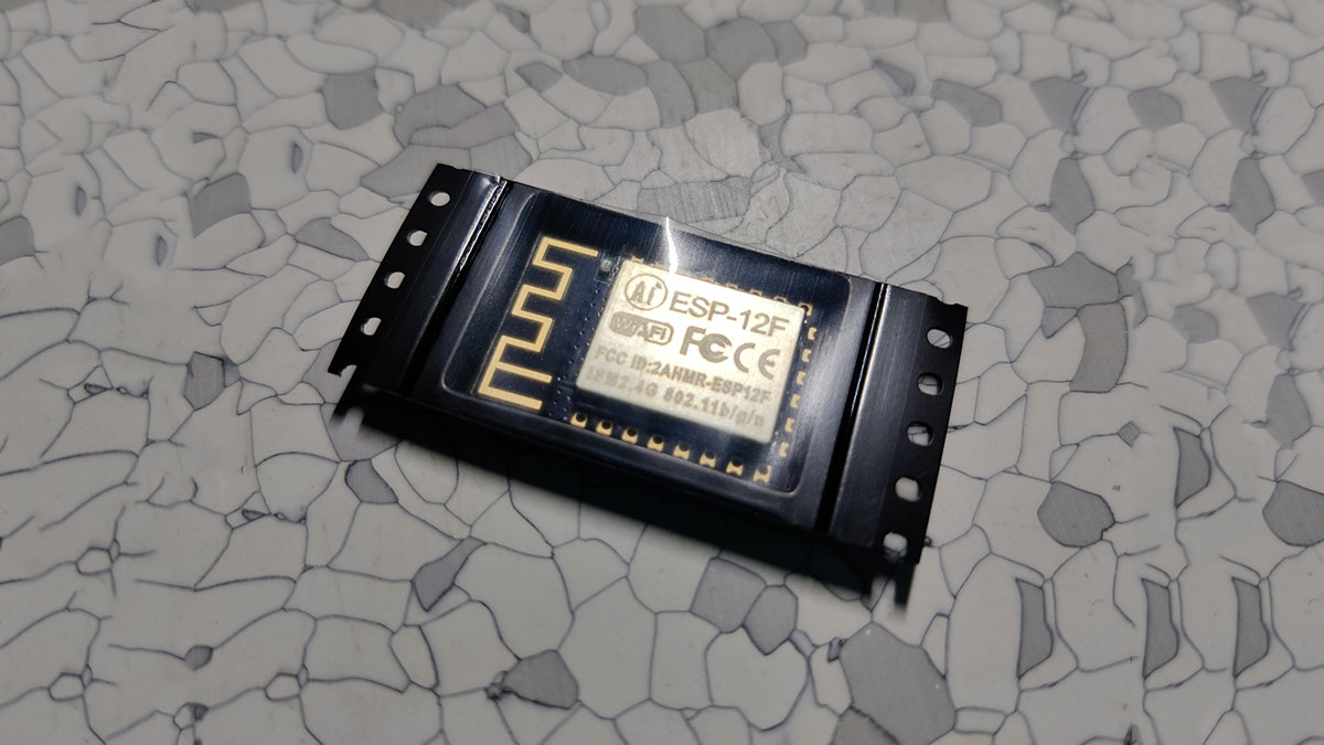
Hey everyone what’s up!
so you got yourself an esp12f module and now you want to program it? here’s how you can do that in an easy way that doesn’t involve that complex FTDI module with the button’s method.
so the easy way is to use a Nodemcu here. actually, the trick is to use the CP2102 chip instead of the esp12f on Nodemcu.
here’s the setup video-
Supplies
We will need the following things for this Instructables!
- CUSTOM PCB (which was provided by JLCPCB)
- TARGET ESP12F Board wth LED soldered
- Nodemcu
- Header pins
Step 1: Getting Setup Ready
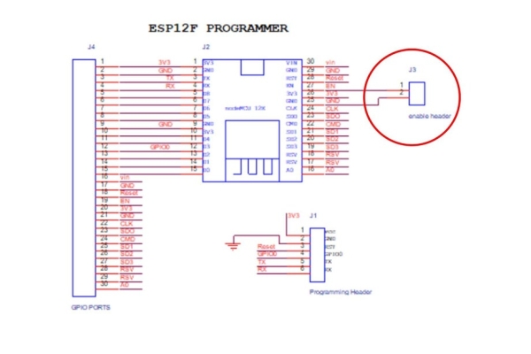
we start first by shorting the Enable pin and GND, this will turn off the esp12f of the Nodemcu and now we can hook an external esp12f setup with the Nodemcu according to the given schematic.
Flashing with Nodemcu instead of using FTDI Module is easier but this doesn’t mean that it’s a proper replacement, for more advanced prototyping with ESP12F in which you need to make a whole setup of ESP12F with a programming IC, you can use the auto-reset method which uses two Transistor to put the esp12f into flash mode.
I’ve added its schematic and this method is basically used in all similar boards even in the Nodemcu.
Step 2: CUSTOM PCB AND ITS ASSEMBLY
I prepared a Programmer PCB for this job, I first design this PCB according to the given schematic and then gave this PCB to jlcpcb for samples and recovered them after a few weeks; you can check them out if you need great PCB service at a low cost! www.jlcpcb.com
This PCB is basically an expansion board for Nodemcu, I have added 31 header pins and additional OLED breakout points so I can use this Setup for something else if it’s not being used as a programmer. The Assembly process of this custom PCB includes adding the header pins to the board with soldering iron and connecting the Nodemcu on those header pins.
Step 3: ESP12F MINIMAL SETUP
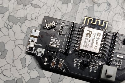
As for the ESP12F Setup, ill be using a board I design for my previous RGB Glasses Project. This PCB breakouts the ESP12F points and also pull down a few necessary pins with a 10K Resistor which is the minimal requirement of driving the ESP12F Board.
For Programming this, I’ve connected the Programming pins which are the 3V, GND, RST, GPIO0, TX, and RX Pins to a CON6 point for adding header pins on it. Basically, I designed this PCB in such a way that I can connect NODEMCU PROGRAMMER PCB with this setup by male and female header pins. It’s a clever method to use as because of this external programmer, we don’t need to add FTDI Chips on ESP12F setup and we can make smaller PCBs and for programming them we just breakout 6 important pins and connect our external programmer with it.
Step 4: WIRING CONNECTIONS
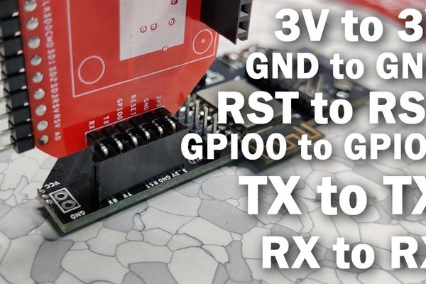
For Programming the ESP12F board, we need to connect the NodeMCU with our ESP12F Setup in this way-
- 3v to 3v
- GND to GND
- RST to RST
- GPIO0 to GPIO0 //D3 is GPIO0 on Nodemcu
- TX to TX
- RX to RX
Also, do not forget to add a Jumper wire between ENA and GND Pin on Nodemcu. this will turn off the ESP12F of the Nodemcu and our external ESP12F will get connected with the Nodemcu’s CP2102 chip.
Step 5: CODE and Flashing Step
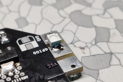
As for the test sketch, I have added an SMD green led between GPIO12 and GND.
I used a simple webserver to connect the esp12f with my phone and just toggle the SMD LED but before that, you need to change the SSID and Password in the Sketch according to your credentials.
- Connect the Nodemcu programmer with the ESP12F Board
- open Arduino ide, plug the USB on Nodemcu
- then go to the Tools menu and select the Nodemcu board that you are using
- select the right port and hit upload
after uploading goto the serial monitor and hit the reset button on Nodemcu. as you can see, our setup has been connected with the smartphone…
now copy this IP address and open this in your web browser,
Step 6: RESULT
Open the Webserver by writing the IP Address in the serial monitor on your smartphone’s web browser and press the LED ON or OFF link to toggle the state of the LED.
And we have successfully programmed an esp12f with a Nodmcu, the webserver sketch can be run with any esp8266 board so you can use that for controlling anything like a relay for example.
Watch the video for better demo-
Source: Program ESP8266 With NodeMCU
- How do I disable the onboard ESP8266 on the NodeMCU?
Short the ENA (Enable) pin to GND to turn off the onboard ESP8266. - What pins are required to program the ESP12F with the NodeMCU?
Connect 3V, GND, RST, GPIO0, TX, and RX between the NodeMCU and the ESP12F. - How should TX and RX be connected between NodeMCU and ESP12F?
Connect TX to TX and RX to RX as described in the article. - Do I need an FTDI module to program the ESP12F in this method?
No, the article uses the NodeMCU CP2102 instead of an FTDI module to program the ESP12F. - What additional PCB features were included on the custom programmer board?
The custom PCB includes 31 header pins and additional OLED breakout points. - What resistor value is used for pull downs on the ESP12F minimal setup?
10K resistors are used to pull down necessary pins on the ESP12F board. - How do I upload code to the ESP12F using this setup?
Connect the NodeMCU programmer to the ESP12F, plug in USB, select the NodeMCU board and port in Arduino IDE, and hit upload. - How do I access the webserver after flashing?
Open the serial monitor, press reset on the NodeMCU, copy the IP address shown, and open it in your smartphone web browser.
