
Summary of The Nerd Watch
This tutorial guides users through building a "Nerd Watch," a binary time-displaying device using an ATtiny chip and surface-mount components. The watch flashes two LEDs to show hours and minutes in binary format upon button press. Construction involves milling a custom PCB with an Othermill, soldering electronic parts, and programming the microcontroller via Arduino.
Parts used in the Nerd Watch:
- Othermill machine
- Computer with Otherplan software
- Alignment bracket and mounting hardware
- Soldering iron
- Flat end mills (1/64", 1/32", and optional 1/16")
- Double-sided FR-1 PCB blank
- Double-sided tape
- Solder and solder paste
- Sewing needle and black thread
- Velcro straps or watch strap
- 8-pin IC socket
- Atmel ATtiny85 chip
- Two SMD LEDs
- Two SMD resistors (~50 ohms)
- Square SMD momentary button
- CR2032 3-volt coin cell battery
- Coin cell battery holder
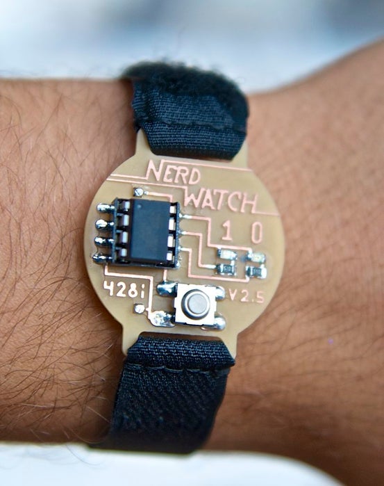
Hello! Welcome to another Other Machine project tutorial! I’m Sam DeRose, a former Other Machine Co. Summer Intern. I created the Nerd Watch last summer while working at OMC.
The Nerd Watch displays the time in binary when the button is pushed. The watch shows the hour and minutes by flashing two LEDs in sequence to represent two 4-bit binary numbers (in big-endian format). Here’s a great description of how to read binary numbers.
I’ll show you how to build a Nerd Watch from scratch with a few electronics components and an Othermill.
This tutorial presumes you have previous experience working with surface-mount electronic components and that you’re no stranger to a multimeter and soldering. It’s also helpful to pick up a little information on how Arduino works.
Step 1: A Few Notes Before We Get Started
How to Tell the Time:
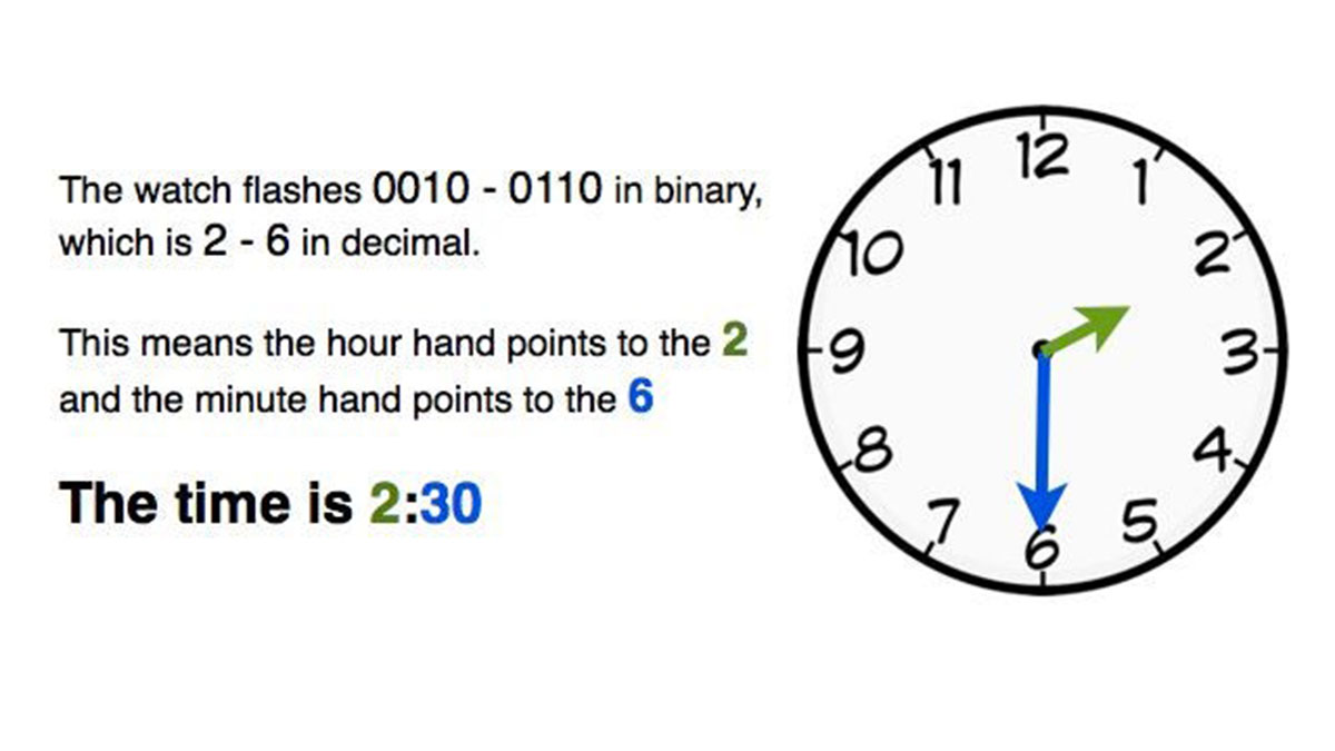
The first number represents the hour and the second number represents the number the minute hand would be pointing to if it were an analog clock. For example, if the watch flashes 0010 – 0110, this corresponds to 2 – 6, which means the hour is 2 and the minute hand points to the 6. It’s 2:30. (Check out the image above for a graphic description!) There’s no indication of a.m. or p.m., but hopefully it’s clear whether it’s 2:30 in the morning or not 🙂
The watch is based on a project my dad made for Maker Faire. It uses the same code and schematic, but now the board is laid out to look more like a watch, and sleeker surface-mount (SMD) components are used to make it lower profile.
Note: I made many iterations of this watch – you’ll see version numbers in the photos. Because of this, the progress pictures in this post skip around between different versions pretty frequently. The general process for every version is exactly the same, though, so don’t worry if your watch doesn’t look exactly like the picture.
Another Note: The main part of this post will cover how to build version 2.5, the most current version that uses a regular ATtiny chip. However, Step 9 shows a variation, version 3.1, which uses a surface-mount ATtiny and a mini-USB port to program it. This version is significantly more difficult to build and program, so I’d recommend starting with version 2.5 and only trying version 3.1 if you feel really ambitious (or have experience with soldering SMD components).
Step 2: How It Works
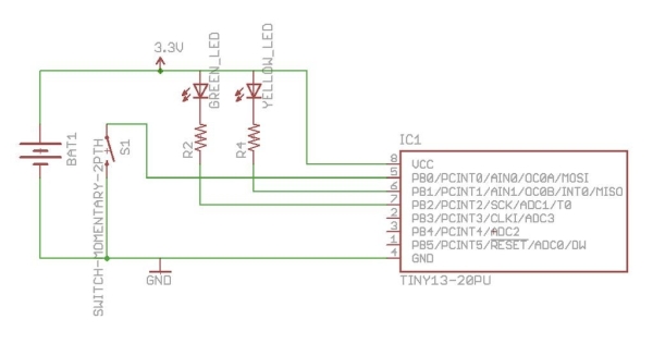
The ATtiny chip (the black 8-pin IC chip) is the heart of the watch. This chip is basically a small version of the same chip that’s inside an Arduino, and thus it can be programmed to perform different functions. In this case, the chip has a program on it that waits for a button press, and when it senses one, it grounds several of its pins so that current can flow from +3 volts through the LEDs, lighting them up. The ATtiny has an internal clock, so the LEDs are programmed to flash to display the time.
Step 3: Tools, Materials, and Files
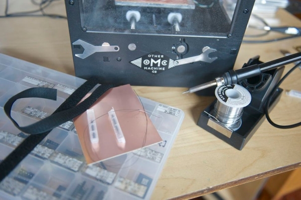
TOOLS
- Othermill
- Computerwith Otherplan installed
- Alignment bracket and mounting hardware included with the Othermill
- Soldering iron
- Flat end mills, 1/64″ and 1/32″
- Flat end mill, 1/16″ for clearing out all excess copper (optional but recommended)
MATERIALS
- Double-sided FR-1 PCB blank
- Double-sided tape
- Solder
- Solder paste
- Sewing needle
- Black thread
- Velcro straps, 3/4″, blackor another form of watch strap
ELECTRONIC COMPONENTS
- IC socket, 8-pin
- Atmel ATtiny chip I used the ATtiny85.
- LEDs, SMD (2)SMD = surface mount device
- Resistors, ~50 ohms, SMD (2) Exact value isn’t important.
- Momentary button, square, SMD I used these, but others will fit too.
- Coin cell battery, CR2032, 3-volt
- Coin cell battery holder
FILES
- EAGLE board file NerdWatchV2.5.brd for the watch
- Arduino sketch NerdWatch.ino to go on the ATTiny. The .zip file included here has the sketch, as well as the libraries you’ll need to install to get the sketch working properly.
- EAGLE file for ATtiny Programmer TinyProgShield.brd (optional)
- NOTE: Remember to install the libraries in Arduino before you try to compile the sketch. Here’s how:
- Download and install Arduino if you haven’t already. You can get it from the Arduino site.
- Download the NerdWatch.zip file and remember where you saved it.
- Launch Arduino. Go to Sketch > Import Library > Add Library and navigate to where you saved NerdWatch.zip.
- Select the whole .zip file, and let Arduino install the libraries automatically.
- Restart Arduino to activate the libraries. Note: If you have any issues, the Arduino Forums are a spectacular place to ask questions for advanced users and new programmers alike.
- Use Arduino to open NerdWatch.ino and compile your code.
For Version 3.1 you’ll need these files:
- EAGLE file NerdWatchV3.1.brd
- NerdWatch.zipsame file as for v2.5
- EAGLE file SMDtinyProgrammer.brd for the SMD ATtiny programmer board
Step 4: Set Up Otherplan
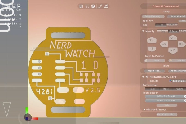
Fire up Otherplan. Then connect your Othermill to your comuter and power it on.
Import the EAGLE file into Otherplan and perform the following steps to set up the cut:
- Use theSetup Fixturing button to walk you through the installation and location of the alignment bracket.
- Once the bracket is installed, set your material to double-sided FR1 board using the Setup Material button.
- In this dialogue, make sure to align the material’s origin to the bracket.
- Use a 1/32″ and 1/64″ flat endmill for the front of the board, and a 1/32″for the back of the board. (The back is also where you might add your optional 1/16″ end mill if you have one and you want to.)
- The default setting for your FR-1 board works fine for this project. If you want to experiment with more trace clearance, you can turn on BitBreaker Mode (Otherplan > Preferences > click on the BitBreaker box) and experiment with the depth and clearance settings (this is for the user who knows their way around a mill).
If you need a refresher on using Otherplan and setting up the Othermill, check out this Getting Started guide.
Read more: The Nerd Watch
-
How does the watch display the time?
The watch displays the hour and minutes by flashing two LEDs in sequence to represent two 4-bit binary numbers in big-endian format. -
What is the function of the ATtiny chip?
The ATtiny chip acts as the heart of the watch; it waits for a button press and then grounds pins to light up LEDs according to its internal clock program. -
Can I see if it is a.m. or p.m.?
No, there is no indication of a.m. or p.m., so you must determine if it is morning or evening based on context. -
Which version is recommended for beginners?
Version 2.5 is recommended because it uses a regular ATtiny chip, whereas version 3.1 uses difficult-to-solder surface-mount components. -
How do I install the required libraries for the code?
You must launch Arduino, go to Sketch > Import Library > Add Library, select the NerdWatch.zip file, and restart Arduino to activate them. -
What end mills are needed for the front of the board?
A 1/32" and a 1/64" flat endmill are required for the front of the board during the milling process. -
Does the project require previous experience?
Yes, the tutorial presumes previous experience working with surface-mount electronic components, using a multimeter, and soldering.
