
Summary of 2 Players Competition/Quiz Buzzer Box System Using Arduino
This article details the creation of a 2-player quiz buzzer system using an Arduino to identify the fastest button pusher. The author initially prototyped the device on a breadboard before building a permanent version on a custom PCB with external switches and LEDs. The project involves designing circuit logic, soldering components, and writing code to handle button inputs and LED outputs for player feedback.
Parts used in the Quiz Buzzer Box System:
- Arduino Nano Clone
- 4 LED lights (white, green, yellow, blue)
- Jumper wires
- 2 push buttons
- 2x 5K resistors
- Breadboard
- PCB (5x10 cm)
- ATMega 328P-PU
- 6 green LEDs
- 1 red LED
- 5 blue LEDs
- 1x 16MHz crystal
- 2x10 uF capacitors
- 10 meters of 2 core telephone wire
- 2x quick release switches
- 1 female micro USB connector
- 1 on/off switch
Story
A bit of background. My brother came to me with an odd box that a friend of his asked someone to make so that they can determine the fastest contestant to push a button. The box consisted of some LEDs, two buttons, and two sets of bicycle bells that made some weird noises. It did light up and make noises, but it did not actually serve the purpose it is made for, which is to actually determine the first competitor to push the button. I told him that I can help, and I searched for an tutorial or a tutorial to make something of the sort using Arduino, however, not knowing the exact name of what I’m searching for didn’t help much, so I set on making one combining whatever it is that I know about Arduino which is not much. Once I finished the project, I found out that it is called a quiz buzzer system (I was searching for a competitors button box), and that there are some cool samples in tutorials that could have saved me a lot of time, but I managed to make something, and I would like to share it with everyone, so here it goes.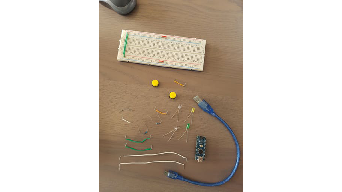
Step 1: Prototype Components
As a proof of concept, I had to prototype the whole thing. I used the following items:
- Arduino Nano Clone
- 4 LED lights (it helps if they are of different colors. I used white, green, yellow, and blue)
- Jumper wires
- 2 push buttons
- 2x 5K resistors
- A breadboard
Step 2: The Actual Box Components
So I am not interested in jailing the nano in a plastic box for eternity. I will make an Arduino on breadboard to do the job, and for this, the components are as follows.
For the circuit I used:
- PCB (I use a 5×10 cm pcb)
- 1x ATMega 328P-PU
- 6 green LEDs
- 1 red LEDs
- 5 blue LEDs
- 1x 16MHz crystal
- 2×10 uF capacitors
- 2x 5K resistors
- 10 meters of 2 core telephone wire
- 2x quick release switches
- 1 female micro USB connector
- 1 on/off switch
The tools I need are a soldering iron, solder, and access to a CNC machine.
Step 3: Sketch Logic
To be able to make sense of the loops and actions that will take place. I drew it on paper, but I think this is a clearer view of the way I envision the whole thing to work.
Step 4: Making the Prototype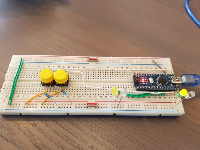
I used the components I had to wire the prototype. It goes this way:
- Place the Arduino on the breadboard
- Place the push buttons
- Connect the resistors to ground and one leg of each button
- Connect the other push button leg to +Ve (I will use 3V3)
- Connect the Arduino 3V3 pin to the +Ve rail of the breadboard and the GND pin to the GND rail of the breadboard
Now you need to figure out the pins you will use. In my code I used the following pins:
- First player LED: 8
- Second player LED: 9
- Green LED: 10
- White LED: 11
- First player button: 12
- Second player button: 13
- Connect each LED to the pin and ground
For the buttons, connect PIN 12 to the leg opposite of the resistor for player 1 button, and PIN 13 to the leg opposite of the resistor for player 2 button. The Fritzing sketch should show the whole thing very clearly.
For more detail: 2 Players Competition/Quiz Buzzer Box System Using Arduino
- What is the primary purpose of this project?
The project determines the fastest contestant to push a button in a two-player competition. - How can I prototype the system before building the final box?
You can use an Arduino Nano Clone, LEDs, jumpers, push buttons, resistors, and a breadboard as a proof of concept. - What microcontroller is used in the final PCB version?
The actual box uses an ATMega 328P-PU chip instead of a pre-made board. - Which pins are assigned to the first player's LED and button?
The first player LED connects to pin 8 and the button connects to pin 12. - What tools are required to build the permanent PCB version?
You need a soldering iron, solder, and access to a CNC machine. - How are the push buttons connected in the prototype circuit?
Resistors connect to ground and one leg of each button, while the other leg connects to +Ve (3V3). - What type of wire is used for the external connections?
The project utilizes 10 meters of 2 core telephone wire for the quick release switches. - Can I change the colors of the LEDs used in the project?
Yes, it helps if they are different colors, such as white, green, yellow, and blue.
