Summary of Wireless Serial using nRF24L01
This project implements a low-cost, reliable bidirectional wireless serial communication system using Arduino Pro Mini 3.3V boards and nRF24L01+ RF modules. It eliminates the need for separate transmitter/receiver configurations by utilizing identical code on both units. The design features a custom software serial routine to expand the buffer capacity to 256 bytes, overcoming standard Arduino limitations. Ideal for robotics, remote sensing, and RC applications, it supports ranges up to 1000 meters with PA/LNA modules while operating efficiently on 3V power.
Parts used in Wireless Serial Communication:
- nRF24L01+ RF Module
- Arduino Pro Mini 3.3V 8MHz
- Arduino Uno (optional alternative)
- External passive components
- 3V battery
This project is very useful in many application where wireless reliable serial communication is required. It give bidirectional communication, You need to have same code in both arduino, no need of separate configuration for receiver or transmitter. It is more advantageous and cost saving than using Xbee, Zegbee Modules.
This circuit is consists of Arduino Pro Mini 3.3V 8MHz and nRF24L01+ RF Module, this make it very low cost and reliable, it can communicate at longer distances when we use nRF24L01+ PA LNA module.
The code is done with most advance possible conditions here I am using custom serial software routine instead of arduino serial to make possible to have 256bytes of serial buffer. arduino have only 64 bytes of serial buffer for longer serial data use of internal buffer causes problems so I made my own serial rutine
Let’s look at its advantages nRF24L01+ modules are very cheap and low power consuming, you can power your circuit using 3V battery also, that’s why I am using Arduino Pro Mini 3.3V 8MHz, you can use any arduino board, only take care that supply to nRF24L01+ module must be 3.3V, nRF24L01+ can take 5V on its IO lines so no need to have any level conversion circuits.
Applications of this projects are limitless you can use it for your robotic applications, remote sensing, wireless remote control, RC air craft as nRF24L01+ PA LNA module can give open air 1000 meter range.
Components required:
1. nRF24L01+ Quantity 2.
2. Two arduino boards.
Introduction to nRF24L01+:
The nRF24L01+ is a single chip 2.4GHz transceiver with an embedded baseband protocol engine, suitable for ultra low power wireless applications. The nRF24L01+ is designed for operation in the world wide ISM frequency band at 2.400-2.4835GHz.
To design a radio system with the nRF24L01+, you simply need an microcontroller and a few external passive components.
You can operate and configure the nRF24L01+ through a Serial Peripheral Interface (SPI). The register map, which is accessible through the SPI, contains all configuration registers in the nRF24L01+ and is accessible in all operation modes of the chip.
The embedded baseband protocol engine is based on paket communication and supports various modes from manual operation to advanced autonomous protocol operation.
Internal FIFOs ensure a smooth data flow between the radio front end and the system’s microcontroller. Enhanced Shock-Burst reduces system cost by handling all the high speed link layer operations.
The radio front end uses GFSK modulation. It has user configurable parameters like frequency channel, output power and air data rate. nRF24L01+ supports an air data rate of 250kbps, 1Mbps and 2Mbps. The high air data rate combined with two power saving modes make the nRF24L01+ very suitable for ultra low power designs.
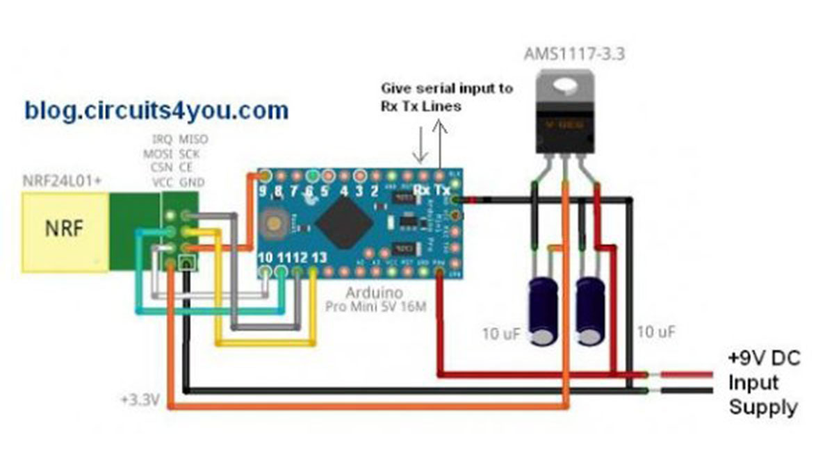
Step 1: Circuit Connections of nRF24L01+ with Arduino Pro Mini you can use Arduino Uno also with same code and connections
Use same code in both arduino boards.
//Blog.Circuits4you.com Wireless serial communication
//26-Jan-2015
//DO NOT FORGET BAUD RATE SETTINGS FOR 8MHz MINI PRO

#include <avr/io.h>
#include <avr/interrupt.h>
#include <SPI.h>
#include "nRF24L01.h"
#include "RF24.h"

RF24 radio(9,10);
const uint64_t pipes[2] = { 0xDEDEDEDEE7LL, 0xDEDEDEDEE9LL };

char SerialBuffer[256] = "";
char RecvPayload[128] = "";
int i,TimeOut=10,dataBufferIndex=0;

void setup() {
  radio.begin();

  radio.setDataRate(RF24_250KBPS);
  radio.setPALevel(RF24_PA_MAX);
  radio.setChannel(70);

  radio.enableDynamicPayloads();
  radio.setRetries(15,15);
  radio.setCRCLength(RF24_CRC_16);

  radio.openWritingPipe(pipes[0]);
  radio.openReadingPipe(1,pipes[1]);

  radio.startListening();


  USART_Init();
  SREG=0x80;
  delay(500);
}

void loop() {
  nRF_receive();

  if(TimeOut==0 && dataBufferIndex>0)
  {
    serial_receive();        // Send this buffer out to radio
  }
  else
  {
    TimeOut--;
  }
}

void USART_vSendByte(char u8Data)
{
  // Wait if a byte is being transmitted
  while((UCSR0A & (1<<UDRE0)) == 0);
  // Transmit data
  UDR0 = u8Data;
}

/****************************************************************************************/
/*                                                                          USART INIT                                        */
/****************************************************************************************/
void USART_Init()
{
  /*Set baud rate */
  UBRR0H = 0;
  UBRR0L = 51;  //103 @ 16MHz  51 @ 8MHz
  //Set double speed enabled
  UCSR0A |= (1<<U2X0);

  /*Enable receiver and transmitter */
  UCSR0B = (1<<RXEN0)|(1<<TXEN0) | (1<<RXCIE0);
  /* Set frame format: 8data, 2stop bit */
  UCSR0C = (1<<USBS0)|(3<<UCSZ00);
}
/****************************************************************************************/
/*           USART ISR                                         */
/****************************************************************************************/
SIGNAL(USART_RX_vect)
{
        char incomingByte = UDR0;
        SerialBuffer[dataBufferIndex++]=incomingByte;
        TimeOut=2000;
 sei();
 return;
}
/****************************************************************************************/
/*                RF Receive                                                            */
/****************************************************************************************/
void nRF_receive(void) {
  int len = 0;
  if ( radio.available() ) {
      bool done = false;
      while ( !done ) {
        len = radio.getDynamicPayloadSize();
        done = radio.read(&RecvPayload,len);
        delay(5);
      }

    RecvPayload[len] = 0; // null terminate string

     for(i=0;i<len;i++)
    {
      USART_vSendByte(RecvPayload[i]);
    }
    RecvPayload[0] = 0;  // Clear the buffers
  }

}

void serial_receive(void)
{
        char SendPayLoad[32];
        // swap TX & Rx addr for writing
        radio.openWritingPipe(pipes[1]);
        radio.openReadingPipe(0,pipes[0]);
        radio.stopListening();

        if(dataBufferIndex<31)      //as nRF24L02 have only 32 byte of buffer to send more bytes it need to be splitted
        {
          bool ok = radio.write(&SerialBuffer,dataBufferIndex);
        }
        else
        {
          for(i=0;i<30;i++)
          {
            SendPayLoad[i]=SerialBuffer[i];
          }
            bool ok = radio.write(&SendPayLoad,30);    //First 30 Bytes are sent

          if((dataBufferIndex-30)<31)    //If remainging bytes are less than 31
          {
              for(i=0;i<(dataBufferIndex-30);i++)
              {
                SendPayLoad[i]=SerialBuffer[i+30];
              }
            bool ok = radio.write(&SendPayLoad,(dataBufferIndex-30));    //Remaining Bytes are sent
          }
          else                            //Remaining bytes are more than 31 i.e total is greater than 60
          {
                      for(i=0;i<30;i++)
                      {
                        SendPayLoad[i]=SerialBuffer[i+30];
                      }
                        bool ok = radio.write(&SendPayLoad,30);    //60 Bytes are sent

                      if((dataBufferIndex-60)<31)    //If remainging bytes are less than 31
                      {
                          for(i=0;i<(dataBufferIndex-30);i++)
                          {
                            SendPayLoad[i]=SerialBuffer[i+60];
                          }
                        bool ok = radio.write(&SendPayLoad,(dataBufferIndex-60));    //Remaining Bytes are sent
                      }
          }
        }
        // restore TX & Rx addr for reading
        radio.openWritingPipe(pipes[0]);
        radio.openReadingPipe(1,pipes[1]);
        radio.startListening();

        SerialBuffer[0] = 0;  // Clear the buffers
        dataBufferIndex = 0;
} // end serial_receive()

#ifndef min
#define min(a,b) ( (a) < (b) ? (a) : (b) )
#endif

void mid(const char *src, size_t start, size_t length, char *dst, size_t dstlen)
{       size_t len = min( dstlen - 1, length);

        strncpy(dst, src + start, len);
        // zero terminate because strncpy() didn't ?
        if(len < length)
                dst[dstlen-1] = 0;
}
Source: Wireless Serial using nRF24L01
- How does this project handle data buffering compared to standard Arduino serial?
The project uses a custom serial software routine to create a 256-byte buffer, whereas standard Arduino serial only has a 64-byte buffer. - Can I use an Arduino Uno instead of the Pro Mini?
Yes, you can use an Arduino Uno with the same code and connections as the Pro Mini. - What voltage must be supplied to the nRF24L01+ module?
The supply to the nRF24L01+ module must be 3.3V, though its IO lines can accept 5V without level conversion circuits. - What is the maximum range achievable with this setup?
Using the nRF24L01+ PA LNA module, the system can achieve an open air range of 1000 meters. - Does this system require different code for the receiver and transmitter?
No, you need to have the same code on both Arduino boards; no separate configuration is required. - What frequency band does the nRF24L01+ operate in?
The module operates in the world-wide ISM frequency band at 2.400-2.4835GHz. - What are some practical applications for this project?
Applications include robotic systems, remote sensing, wireless remote control, and RC aircraft. - How is the nRF24L01+ configured and operated?
You can operate and configure the module through a Serial Peripheral Interface (SPI) to access its register map.