
Summary of Miniscope v2e
This article describes a low-cost, single-channel USB oscilloscope based on the STM32F042 microcontroller. It streams 8-bit data at 480 kSps to a PC via USB FS, utilizing a DLL and Win32 GUI for control. The design emphasizes minimalism with a single-sided PCB, crystal-less USB support, and an embedded DFU bootloader for easy firmware updates.
Parts used in Miniscope v2e:
- STM32F042F4 microcontroller
- Voltage regulator (3V or 3.3V)
- Mini-USB connector
- Passive SMD components
- R8 resistor (27k)
- R4 resistor (51k)
- SMD microswitch (or jumper)
- Single-sided PCB
Extremely cheap low-speed PC/USB oscilloscope with STM32 (STM32F042) microcontroller.
Quick specification
- follows miniscope v2a-d idea: very simple device streaming data in real time to PC; DLL and GUI (Win32) are handling all the functionality,
- sampling: 480 kSps, 8 bit, single voltage range, streaming via USB FS with libusb (32/64bit) used as driver,
- record length: 4k to 1M defined in DLL; up to 512M samples when recording to file,
- firmware loading via USB (DFU bootloader embedded in ROM),
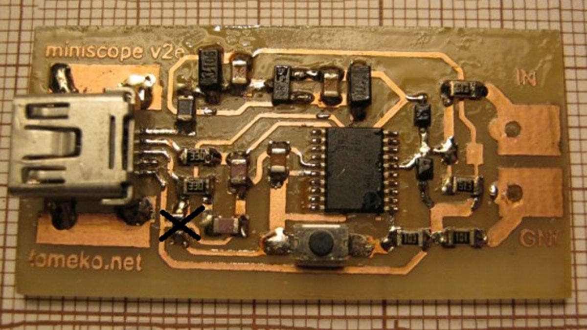
- low component count: MCU, voltage regulator, mini-USB and few passive SMD components on single-sided PCB.
Announced in January 2014 Cortex-M0 microcontroller family that features crystal-less USB FS device allows to cut noticeable part of BOM when building oscilloscope/recorder similar to miniscope v2c/v2d. STM32F042F devices are interesting in particular because of small and friendly TSSOP20 package with minimum number or power lines.
STM32F042F4 devices feature USB bootloader (DFU), single 1MSps ADC (so single channel sampling would be preferred to avoid crosstalk issues), 16 kB FLASH memory (~2 times more than needed) and 6 kB RAM.
Schematic
miniscope_v2e_20140501.pdf
1k5 USB pull-up should not be mounted as STM32F042 has internal pull-up – apparently used by ROM DFU bootloader also.
Version from 2015.02.20 is intended to use R8 27k and R4 51k for input divider.
Either 3V (that is one I’ve actually used) or 3.3V voltage regulator can be used.
Comparing this schematic with Discovery kit for STM32F072 indicates that few other passive components (RC at USB D+/D-) may be redundant.
If you do not plan to experiment with firmware heavily (or don’t mind some hanging wires at the time) you can replace SMD microswitch with some sort of jumper as it is needed only for firmware upgrading.
For More Details: Miniscope v2e
-
What microcontroller is used in this project?
The device uses the STM32F042F4 Cortex-M0 microcontroller. -
Does the STM32F042 require an external crystal for USB?
No, the STM32F042 features a crystal-less USB FS device capability. -
How is the sampling rate specified for this oscilloscope?
The sampling rate is 480 kSps with 8-bit resolution. -
Can I use a 3V voltage regulator instead of 3.3V?
Yes, either a 3V or 3.3V voltage regulator can be used. -
Is the 1k5 USB pull-up resistor required on the PCB?
No, it should not be mounted because the STM32F042 has an internal pull-up. -
How is firmware loaded onto the device?
Firmware is loaded via USB using the embedded DFU bootloader. -
What interface handles the functionality on the PC side?
A DLL and a Win32 GUI handle all the functionality. -
Can the SMD microswitch be replaced?
Yes, it can be replaced with a jumper if you do not plan to experiment heavily with firmware.
