
Summary of Scooterputer
The author upgraded a scooter with an Arduino Duemilanove-based "Scooterputer" to monitor battery voltage, temperature, time, speed, and location. Initially designed as a simple battery indicator, the project evolved to include a TouchShield Slide OLED display for comprehensive data readouts like GPS coordinates and compass heading. The system uses a sensor shield stacked under the scooter's hood, connected to a removable display via an Ethernet cable, ensuring functionality even if the display is detached.
Parts used in the Scooterputer:
- Arduino Duemilanove
- Liquidware TouchShield Slide OLED display with touch screen
- DS18B20 temperature sensor
- DS1307 RTC chip
- Accelerometer
- GPS chip
- GSM/GPRS quad-band cellular module
- Proto Shield PCB from Adafruit Industries
- Breakout boards for surface mount chips
- 30 gauge Kynar solid wire
- Right-angle pin headers
- Straight pin headers
- Standard 8-wire ethernet cable (CAT-5 connector)
- Solid telephone wire
- 3.3v regulator
- 10k resistor
- 1N914 diode
I spend a fair amount of time zipping around town on my scooter, and thought it would be cool to add a voltage monitor to warn when the battery might need recharging. Waiting until the electric starter no longer works is somehow lacking. So after an evening with an Arduino Duemilanove, I had a simple programmable voltage divider with 3 LEDs indicating battery low, good, and charging. Done.
That’s when I saw Liquidware’s very cool TouchShield Slide OLED display with touch screen. It was telling me it wanted to be on my scooter. It’s a bit overkill for just battery status, so I added temperature and time/date readouts. I went to Sparkfun.com and found a DS18B20 temperature sensor and a DS1307 RTC chip. Perfect. Oh wait, what’s this…an accelerometer? Sweet! Hey, a GPS chip…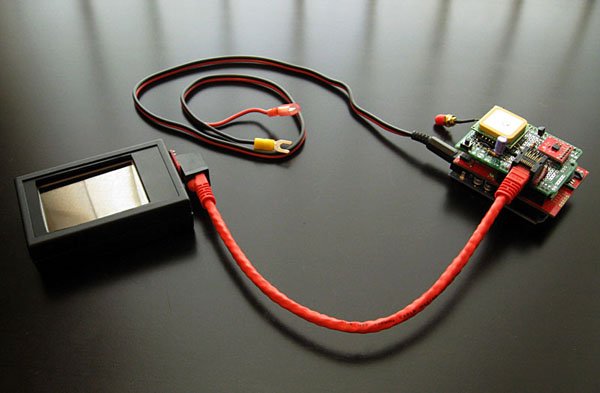 So a few weeks later, here’s what my battery voltage indicator is looking like: You can see in the first photo that the TouchShield display is separated from the Duemilanove / Cell Module / Sensor shields. These are installed “under the hood” of my scooter and provide power and signals to the display module via a standard 8-wire ethernet cable. This keeps the sensors (accelerometer, GPS, cell module, etc.) with the scooter making it functional even without the removable external display, as we’ll see later. (NOTE: this photo was taken before the display was fully mounted inside the enclosure, and is shown without the protective rubber boot.)
Features
- Battery voltage indicator
- Time and date
- Temperature
- Lean gauge with resettable max L-R indicators
- Current speed
- Resettable max speed indicator
- Odometer
- 2 resettable trip meters
- Latitude and longitude readouts
- Compass heading readout
- GSM/GPRS quad-band cellular module
Sensor Shield
The sensors are mounted on a Proto Shield PCB from Ladyada’s Adafruit Industries (which is also where I get my Duemilanoves). Most of the wiring was done using 30 gauge Kynar solid wire, with heavier gauge used for some power and ground connections. Good mechanical connections are important considering the shock and vibrations this will be subjected to.
I went with breakout boards for the surface mount chips. They take up a bit more real estate on the PCB but are very easy to solder and save a lot of construction time. Note the DS1307 RTC on the underside…the profile is still low enough to allow the parts to fit nicely in the open space between boards when stacked. I soldered a right-angle pin header directly to the pads of the GPS breakout board, and straight pin headers on the others.
You might be wondering why I even included the RTC chip since time-of-day and date can be gotten from the GPS data. The DS1307 RTC chip also has 56 bytes of non-volatile RAM. I’m using these registers for storing the trip meter and odometer values so they can be restored between power cycles.
The GPS uses pins 0 and 1 for its TxD and RxD signals to communicate to the Duemilanove. The TouchShield Slide also uses these pins for downloading sketches. The “Program Switch” is used to disconnect the TouchShield Slide from these pins when not downloading so they’re free for use by the GPS. Fortunately the TouchShield Slide uses pins 2 and 3 during normal operation, which I’m driving with digital I/O pins 4 and 5 on the Duemilanove.
Three devices require serial communications (GPS, TouchShield Slide, and Cell Module), and it was a real challenge getting the Duemilanove to support these at data rates needed for the desired performance. Having the GPS, running at 9600 baud, use the hardware serial port (pins 0 and 1) proved to be the best approach. The TouchShield Slide (19200 baud) and Cell Module (4800 baud) use digital I/O pins, and Mikal Hart’s NewSoftSerial library for ‘software’ interrupt driven serial communications was invaluable in getting these to play nicely together.
 The GPS chip is powered by the 3.3v regulator. The 10k resistor and 1N914 diode circuit on the serial RxD line of the chip are used to dampen the 5v signal from the Arduino hardware TxD line used to send data to the chip. When that line is high, the diode doesn’t conduct allowing the 10k pull up resistor to apply a 3.3v high to the GPS RxD input. When it’s low, the diode conducts and the line sinks through the TxD driver pulling the line down. The .7 volt drop across the diode is still sufficient for a low to be recognized by the GPS RxD input. A schottky diode with a .2v drop might be an improvement here, but the 1N914 seems to work fine. The GPS is rarely receiving data anyways – data is usually sent only one time to initialize the NMEA sentences to be sent, the baud rate, and the update cycle rate.
Display
The TouchShield Slide is mounted on another Proto Shield PCB. The CAT-5 connector is wired to the PCB using solid telephone wire to provide power and ground, and to connect the RxD and TxD signals from the Duemilanove to the display. Another line is brought up to drive the beeper.
For more detail: Scooterputer
- Why was the DS1307 RTC chip included when GPS provides time?
The DS1307 RTC chip includes 56 bytes of non-volatile RAM used to store trip meter and odometer values so they are restored between power cycles. - How does the system handle serial communication conflicts between multiple devices?
The GPS uses the hardware serial port on pins 0 and 1, while the TouchShield Slide and Cell Module use digital I/O pins with Mikal Hart's NewSoftSerial library for software interrupt driven communications. - What method is used to connect the sensors to the external display?
The sensors installed under the hood provide power and signals to the display module via a standard 8-wire ethernet cable. - How is the 5v signal from the Arduino protected for the 3.3v GPS chip?
A 10k resistor and 1N914 diode circuit dampen the 5v signal, allowing the pull-up resistor to apply 3.3v high or the TxD driver to sink the line low. - Why were breakout boards chosen for the surface mount chips?
Breakout boards were selected because they are easy to solder and save construction time, despite taking up more real estate on the PCB. - What type of wire was primarily used for wiring the sensors?
Most wiring was done using 30 gauge Kynar solid wire, with heavier gauge used for some power and ground connections to withstand shock and vibration. - Which pins on the Duemilanove drive the TouchShield Slide during normal operation?
The TouchShield Slide uses pins 2 and 3 during normal operation, which are driven by digital I/O pins 4 and 5 on the Duemilanove. - Can the scooter functions work without the removable external display?
Yes, keeping the sensors with the scooter makes it functional even without the removable external display.
