
Summary of How to Build a Simple Force Sensing Resistor (FSR) Circuit
This article explains how to build a circuit using an Arduino and a Force Sensing Resistor (FSR) to detect pressure. The FSR acts as a variable resistor, changing resistance from infinite to 200Ω under pressure. By connecting it in series with a fixed resistor to create a voltage divider, the Arduino reads voltage changes to determine applied force. This setup can be used for applications like detecting passenger presence in car seats to trigger warning lights.
Parts used in the FSR Circuit:
- Force sensing resistor
- 10KΩ Resistor
- Arduino Board
In this article, we will go over how to connect a force sensing resistor, or force sensitive resistor, (FSR) to a circuit to build many different types of useful circuits with them.
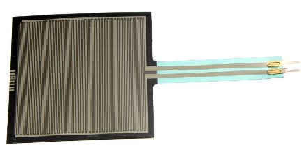
Force sensing resistors are variable resistors which change resistance according to the pressure or force applied to them. Under no force, the resistance is very high, pretty much infinite. When a light pressure is applied to the sensor, its resistance drops to about 100KΩ. When maximum pressure is applied, its resistance drops to about 200Ω.
So with no pressure or weight applied, the FSR circuit will be essentially open because its resistance is so high.
With a good amount of pressure applied, about 20lbs needed, the resistance drops dramatically and can go as low as 200Ω.
We will use the basic functioning principles that FSRs have to create a meaningful circuit.
We will wire an FSR to an arduino board. We wire a 10KΩ resistor in series with the force sensing resistor in order to create a voltage divider. One terminal of the FSR will connect to the 5-volt voltage supply of the arduino board and the other terminal will connect to ground. The 5 volts of voltage will be divided based on the resistance of the fixed resistor and the FSR. The fixed resistor will always stay 10KΩ. However, the FSR serves as the variable resistor. It will change resistance based on the pressure applied to its surface. When there is no pressure applied, its resistance is very high, so most of the voltage falls across it rather than the 10KΩ resistor. When it is pressed against with maximum pressure, its resistance falls to near 200Ω, so most of the voltage falls across the 10KΩ resistor and not the FSR.
Based on these voltage divisions, we can get readings of how much pressure it is being applied to the FSR. If a high voltage is across it, we know that it barely has any pressure applied to it. If a low voltage is across it, then it has a lot of pressure applied to it. The arduino serves as a microcontroller that can give us “pressure” readings of the FSR circuit.
This type of circuit could be useful for a wide range of real-life scenarios. Think of a car seat that is equipped with a seatbelt light on the car dashboard. How does it know to light the dashboard, indicating that the passenger seatbelt is not on? How does it know that a passenger is present in the passenger seat or not? It knows because it detects weight. If it detects weight and the seatbelt is not on, the seatbelt LED on the dashboard lights up, indicating that the seatbelt is not on.
We could apply this circuit that we’re going to build for a situation such as the car seatbelt lights. If our FSR has a very low voltage, this indicates that a lot of pressure is being applied to it. This would indicate that a passenger is present in the seat. If this is the case and the seatbelt is not on, this would trigger the passenger seatlight light to turn on in the dashboard.
Parts Needed for the FSR Circuit
- Force sensing resistor
- 10KΩ Resistor
- Arduino Board
The force sensing resistor can be obtained from many different online retailers. It can be bought in a circular form or square form. A great selection can be found at digikey at the following link: Digikey- Force sensing resistors.
We will use 5 volts of power from the 5V terminal of the arduino.
FSR Circuit
The circuit we will build is shown below:
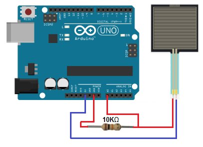
Again, the 10KΩ resistor is in series with the FSR. This forms a voltage divider circuit with the 5 volts powering it. This 5 volts will be divided between the 2 components, based on the resistance of each of the components. Based on the voltage across the components, the arduino board can read how much pressure is being applied to the FSR.
For more detail: How to Build a Simple Force Sensing Resistor (FSR) Circuit
- How does a force sensing resistor work?
It is a variable resistor that changes resistance based on pressure or force applied, dropping from very high resistance to about 200Ω under maximum pressure. - What components are needed to build this circuit?
You need a force sensing resistor, a 10KΩ resistor, and an Arduino board. - How is the FSR connected to the Arduino?
The FSR is wired in series with a 10KΩ resistor to form a voltage divider, with one terminal connected to the 5-volt supply and the other to ground. - Does the resistance of the FSR change with pressure?
Yes, its resistance drops dramatically when pressure is applied, going from nearly infinite to about 200Ω. - Can an Arduino read pressure levels from this circuit?
Yes, the Arduino serves as a microcontroller that provides readings based on the voltage division across the components. - What happens to the voltage when no pressure is applied?
Most of the voltage falls across the FSR because its resistance is very high when there is no pressure. - What indicates a lot of pressure is being applied?
A low voltage across the FSR indicates that a lot of pressure is being applied. - How can this circuit be used in a real-life scenario?
It can detect weight in a car seat to trigger a dashboard light if a passenger is present but not wearing a seatbelt.