
Summary of Arduino-Based Optical Tachometer
This article details the construction of an Arduino-based optical tachometer designed to measure the speed of a Beakman's Electric Motor, originally proposed as a science fair project. The author combines a microcontroller with an IR emitter/detector pair to create a precise measurement tool for educational experiments involving magnets, batteries, and coil variations.
Parts used in the Arduino-Based Optical Tachometer:
- Arduino Diecimila Board
- Computer with Arduino software and USB cable
- IR LED and IR phototransistor
- Visible light LED (high-brightness red)
- 10K Ohm resistor
- 220 Ohm resistor
- Breadboard (semi-optional)
- Hookup wires and clips
- Opaque tape (black electrical tape)
- Framework for holding LED and detector (e.g., KNex pieces)
- Beakman's Electric Motor or similar device
Over ten years ago, I put up a web page with detailed instructions on building a simple electric motor based on one from the Beakman’s World TV show. I called it the “Beakman’s Electric Motor” page and over the years it has had hundreds of thousands, if not millions, of hits. Realizing that just building a motor, no matter how cool, wasn’t a good science fair project, I added suggestions for using the motor as a science fair project, such as experimenting with different magnets, batteries, and coil constructions and seeing how they affect performance. In order to do this, the speed of the motor should be measured, but I left that as an open-ended question.
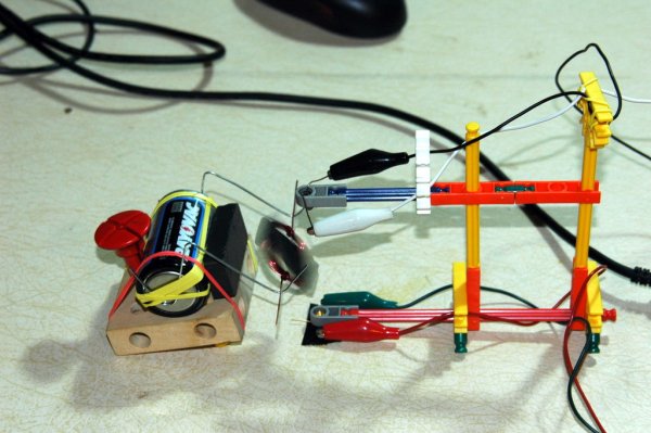
I’ve had dozens of e-mails over the years asking how to measure the speed and I’ve always suggested using a broken light beam and a counter, but I’ve never built one myself. I even suggested to one person that they use a slot-car lap counter since I’d seen on one sale at Toys ‘R Us for 99 cents and she said that it worked perfectly, but not everyone can find a good deal like that.
It just so happened that I got one of these “how do I measure the motor speed?” e-mails on the same day my new Arduino Diecimila microcontroller board arrived from the Make Store, so I thought that would make a great weekend project.
Here is the result, an optical tachometer for Beakman’s Electric Motor using an IR emitter/detector pair and a Arduino board. With a few modifications to the programming, you can use this tachometer for measuring other things such as fan or propeller speed. Notes are included on what to change for different applications.
How to have fun with Arduino is a good source of basics on how to setup and use the Arduino board.
Step 1: Materials Needed
Arduino Diecimila Board
Available from the Make Store or from several other online resources. Note however that the techniques of this Instructable could be adapted for other microcontrollers and circuits.
Computer with Arduino software and USB cable
IR LED and IR phototransistor
I used a Radio Shack #276-142, but that may be an old part number. Parts selection on this probably isn’t too critical.
Visible light LED
I used a high-brightness red one that I had around. Actual selection not too critical.
10K Ohm resistor
220 Ohm resistor
Breadboard (semi-optional), hookup wires, clips
Opaque tape, such as black electrical tape
Framework for holding LED and detector
Use your imagination, I used KNex pieces to build a frame.
Beakman’s Electric Motor (or something else to measure)
Original instructions for building the motor are here: Beakman’s Motor
Similar plans are available from other places, such as this Instructable:
Simple Electric Motor
Step 2: Building and Preparing the Motor (if necessary)
Follow the instructions to build the Beakman’s Electric motor. The motor should be mounted on a suitable base so that it can run freestanding a bit off the table. I used some Brio construction set pieces (I have a lot of toys laying around).
The most important thing to ensure reliable motor operation is to make sure the coil is balanced and the tails of the coil are very straight. I drew a diagram using my coil form and a ruler, then laid the completed coil on the paper to align the tails perpendicular to the coil and to make sure they were straight. I then used a drop of superglue where the tails were wrapped around the coil to make sure they couldn’t slide.
To enable the coil to break the light-beam, place a piece of opaque tape (I used black electrical tape) across the coil. This might slow it down a tiny bit, but if all of your coils have the same sized piece of tape in the same position, your results between coils should be relatively consistent.
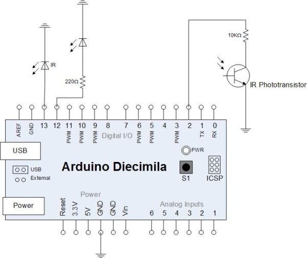
There are three separate circuits to connect to the Arduino. You can refer to my schematic and notes sketch in the images and to the pictures of the breadboard to see how I hooked it all up. Of course, the critical things to note are the anode/cathode orientation of the LEDs and transistors and the connections to power and ground. The whole circuit is powered from the Arduino board and since the program will communicate with the PC, I’m using the USB connector for power.
For more detail: Arduino-Based Optical Tachometer
-
How can I measure the speed of the electric motor?
You can use an optical tachometer consisting of an IR emitter/detector pair connected to an Arduino board. -
Can this tachometer be used for other objects besides the motor?
Yes, with modifications to the programming, it can measure the speed of fans or propellers. -
What is the best way to ensure reliable motor operation during testing?
Ensure the coil is balanced and the tails are very straight, using superglue to prevent sliding. -
Does the opaque tape affect the motor speed?
The tape might slow the motor down a tiny bit, but results remain consistent if all coils have the same sized piece in the same position. -
How is the circuit powered in this project?
The whole circuit is powered from the Arduino board using the USB connector for power. -
What specific parts are needed for the IR detection system?
An IR LED and an IR phototransistor are required to form the light beam that the motor interrupts. -
Is a breadboard mandatory for building this setup?
No, a breadboard is listed as semi-optional, though hookup wires and clips are still needed.
