
Summary of LCD & Keypad Shield Quickstart Guide using arduino
The article explains using the 16x2 LCD & Keypad Shield with Arduino, covering power needs, the LiquidCrystal library, example code, how five buttons share analog pin A0 via a resistor ladder, and a complex example demonstrating button labels and backlight control. It lists pin usage, button ADC voltages, and troubleshooting tips for undervoltage symptoms and powering via a 7–9V DC jack for reliable backlight/contrast.
Parts used in the 16x2 LCD And Keypad Shield Project:
- 16x2 LCD & Keypad Shield
- Arduino board (compatible with LiquidCrystal library)
- 5V quality power source (or 7–9V DC supply to Arduino 2.1mm jack)
- USB cable (for Arduino power via USB)
- Resistor ladder on shield (includes 2K, 330R, 620R and other resistors)
- Wires or headers to connect shield to Arduino pins
- Arduino IDE with LiquidCrystal library
Power Requirements
A quality 5V power source is essential for the LCD & Keypad Shield to achieve maximum backlight and display contrast. Using the LCD Shield along with the Arduino powered by USB might lead to a voltage decrease through the cable. If you are experiencing issues with the contrast of the display or the brightness of the backlight, attempt connecting a power source of approximately 7 to 9Vdc to the Arduino’s 2.1mm DC jack. In an undervoltage scenario, a common sign is when one line of the LCD displays light-colored rectangles instead of characters, while the other line remains blank. The Arduino can still operate properly at around 4V, but the LCD & Keypad Shield will not work.
Library Requirements
The LiquidCrystal library, included in the official Arduino distribution, manages all the tasks associated with interfacing with the LCD Shield. To determine if it is installed, open the IDE and navigate to Files -> Examples -> LiquidCrystal. If it is present, you are all set.
Minimal Display Example
To start up the LCD and display a message, open a new sketch in the Arduino IDE and paste in the following code:
#include <Wire.h>
#include <LiquidCrystal.h>
LiquidCrystal lcd( 8, 9, 4, 5, 6, 7 );
void setup(){ lcd.begin(16, 2); lcd.print(“hello, world!”);}
void loop(){ // your main loop code here…}
Reading The Buttons
The LCD Shield has 5 buttons intended for navigation or control input. The buttons are organized in a convenient layout and named UP, DOWN, LEFT, RIGHT, and SELECT, however it is completely up to your design to determine the action taken when a specific button is pushed.
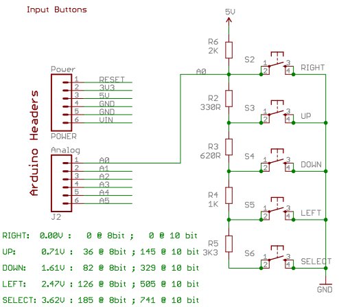
A chain of resistors connects all buttons to a single analog input A0, providing a unique reference voltage to A0 based on the pressed button. This part of the shield diagram displays the input buttons and corresponding resistors.
If no button is pressed, the voltage on A0 will be raised to 5V by the 2K resistor known as R6. None of the other resistors play a role in that scenario, and the analog reading on A0 will max out at 1023. So, if you use the analogRead() function on A0 and the result is 1023 (or higher than approximately 1000), you can conclude that no buttons are currently being pressed.
Now imagine the outcome when the “DOWN” button is pushed. Currently, A0 is receiving a voltage that is split between the 2K resistor attempting to pull it to 5V, and the series of 330R and 620R resistors (totaling 950R) attempting to pull it to 0V. In this scenario, A0 receives a voltage of approximately 1.61V, causing an analogRead() on A0 to result in a value of around 329. If A0 reads around 329, then it means the “DOWN” button is being pressed.
The same concept is valid for the remaining buttons, with their respective voltages and corresponding analogRead() values displayed in the above diagram.
This is an efficient method to have a complete set of input buttons with just one I/O pin on your Arduino, allowing other pins to be available for your project.
Complex Example
The following detailed example uses various methods to illustrate how to display messages on the LCD, read input from buttons, and update the display message based on the button inputs.
Sample code for the Freetronics LCD & Keypad Shield:
http://www.freetronics.com/products/lcd-keypad-shield
by Marc Alexander, 7 September 2011
This example code is in the public domain.
This program demonstrates button detection, LCD text/number printing,
and LCD backlight control on the Freetronics LCD & Keypad Shield, connected to an Arduino board.
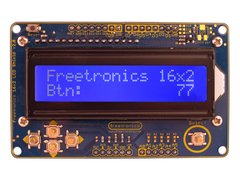
After powerup, the screen looks like this:
|Freetronics 16×2|
|Btn: 0 | <- This time value counts up the number of seconds since reset (overflows at 99)
When a button is pressed, a label appears for it:
|Freetronics 16×2|
|Btn:RIGHT 0 |
Labels are LEFT, UP, DOWN, RIGHT and SELECT-FLASH.
SELECT-FLASH makes the LCD backlight flash off and on when held down.
Pins used by LCD & Keypad Shield:
A0: Buttons, analog input from voltage ladder
D4: LCD bit 4
D5: LCD bit 5
D6: LCD bit 6
D7: LCD bit 7
D8: LCD RS
D9: LCD E
D3: LCD Backlight (high = on, also has pullup high so default is on)
ADC voltages for the 5 buttons on analog input pin A0:
RIGHT: 0.00V : 0 @ 8bit ; 0 @ 10 bit
UP: 0.71V : 36 @ 8bit ; 145 @ 10 bit
DOWN: 1.61V : 82 @ 8bit ; 329 @ 10 bit
LEFT: 2.47V : 126 @ 8bit ; 505 @ 10 bit
SELECT: 3.62V : 185 @ 8bit ; 741 @ 10 bit*/
For more detail: LCD & Keypad Shield Quickstart Guide
- How do I display text on the LCD Shield?
Use the LiquidCrystal library, initialize with lcd.begin(16,2) and call lcd.print with your message as shown in the minimal example. - Can I power the LCD Shield from the Arduino USB?
Yes, but USB power may cause reduced backlight or contrast; using a 7 to 9V DC supply on the Arduino DC jack is recommended for full brightness. - What indicates undervoltage on the LCD?
One line showing light-colored rectangles instead of characters while the other line is blank indicates undervoltage for the LCD Shield. - How are the five buttons read with one pin?
The buttons form a resistor ladder that provides distinct voltages to analog input A0, allowing detection of each button via analogRead. - Does the shield require any special library?
No special library; it uses the standard LiquidCrystal library included with the Arduino distribution. - What Arduino pins does the shield use?
The shield uses A0 for buttons, D4-D7 for LCD data bits, D8 for RS, D9 for E, and D3 for backlight control. - What ADC values correspond to each button on A0?
At 10-bit ADC: RIGHT 0, UP 145, DOWN 329, LEFT 505, SELECT 741 (approximate values listed in the article). - How can I make the backlight flash with a button?
The sample code implements SELECT-FLASH that flashes the LCD backlight when the select button is held.
