
Summary of Soldering Robot – Head Assembly
The project describes a soldering iron slider and stepper mount for a soldering robot head, using 6mm rails, drylin® parts, precision aluminium shafts, and a stepper-driven cord to control vertical motion, with spring-loaded pressure and a reflective sensor for homing. Solder is tube-fed by a stepper-driven roller into a flexible tube and adjustable metal feed to the tip. Components are mounted on milled aluminium plates bolted to a slotted base for frame mounting; design files available as PDF and a test video shows an Arduino-driven stepper.
Parts used in the Soldering Robot Head Assembly:
- 6mm rails
- drylin accessories
- Precision aluminium shaft 100mm length (part no: AWMP-06)
- drylin R – Bearings (part no: RJZM-01-06)
- Milled 6mm aluminium plates
- 4mm aluminium base with slots
- Small compression spring for pressure
- Stepper motor with pulley and cord
- Reflective photo sensor
- Tube feed assembly for solder (flexible tube)
- Stepper motor and roller for solder feed
- Short adjustable metal tube to feed solder to the tip
- Arduino Uno and stepper driver (used in test)
We have finished the soldering iron element slider system and stepper mount for the new soldering robot project.
The soldering iron element slides on a pair or 6mm rails, drylin® accessories, precision aluminium shaft 100mm length (part no: AWMP-06) with drylin® R – Bearings (part no: RJZM-01-06) from www.igus.co.uk which are mounted into milled 6mm aluminium plates. These are bolted to a 4mm aluminium base which has slots milled to allow it to be mounted onto a horizontal frame above the board to be soldered. The design files for the head assembly can be download in PDF format Download PDF
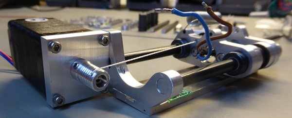
The slides use a small spring to pull the soldering iron onto the PCB and ensure an even pressure while heating and soldering, a stepper motor with a pulley and cord is used to pull the assembly back up and away from the PCB. A reflective photo sensor is mounted near the top of the travel to allow the slides to be homed by the software and stepper system.
The solder will be fed to the soldering iron tip by tube feed in a similar way to the filament feed systems on 3D printers with a stepper motor and roller to drive the solder into a flexible tube which is mounted on the slider and a short adjustable metal tube to feed the solder to the tip.
The video below shows the first test of the stepper motor being driven with an Arduino Uno and stepper driver running at approx 200mA with a 20V supply.
For more detail: Soldering Robot – Head Assembly
- What rails and bearings are used for the slider?
The slider uses 6mm rails with drylin accessories and drylin R bearings part no: RJZM-01-06. - What shaft part is used in the sliding assembly?
A precision aluminium shaft 100mm length part no: AWMP-06 is used. - How is consistent pressure applied to the PCB during soldering?
A small spring pulls the soldering iron onto the PCB to ensure even pressure while heating and soldering. - How is the slider retracted away from the PCB?
A stepper motor with a pulley and cord pulls the assembly back up and away from the PCB. - How does the system detect the home position of the slides?
A reflective photo sensor is mounted near the top of travel to allow homing by the software and stepper system. - How is solder delivered to the iron tip?
Solder is tube-fed similar to 3D printer filament systems, using a stepper motor and roller driving solder into a flexible tube and short adjustable metal feed tube to the tip. - How are the components mounted to the robot frame?
Parts are mounted into milled 6mm aluminium plates bolted to a slotted 4mm aluminium base for mounting onto a horizontal frame above the PCB. - Are design files available for the head assembly?
Yes, the design files for the head assembly can be downloaded in PDF format. - What was used to test the stepper motor?
The first test used an Arduino Uno and a stepper driver running at about 200mA with a 20V supply.