
Summary of Arduino BlinkyBall Project
This article details a DIY 128-LED spherical light project inspired by Nikolai's design. Due to budget constraints and lack of PCB fabrication experience, the author hand-cut circular boards from rectangular stock and reduced the slice count. The sphere uses an Arduino Nano, shift registers, LEDs, resistors, a LiPo battery, and a Parallax accelerometer for orientation. The project features a spiral animation and is powered via a USB mini port, offering approximately 45 minutes of runtime after a one-hour charge.
Parts used in the LED Ball Project:
- Rectangular 2200 hole PCBs from RadioShack
- Circular PCBs from RadioShack (middle size)
- Eight-bit shift registers (16 total across 8 slices)
- 128 LEDs (16 per slice)
- 16 resistors per slice
- Arduino Nano 3.1 from Makershed.com
- LiPo battery and charger from Sparkfun.com
- Parallax Mesmic 2125 accelerometer
- Dremel tool for cutting slits
- USB mini port for charging
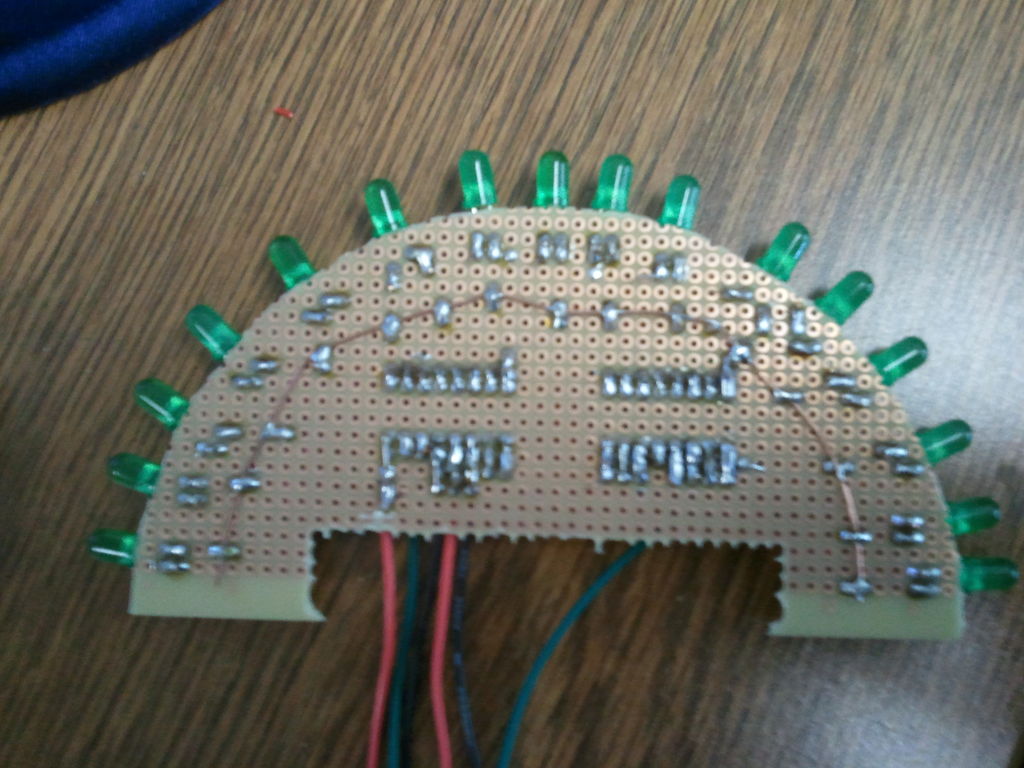
I started off with rectangular 2200 hole PCB’s from RadioShack and using cutting dykes I made half circle boards with a cutout in the center to to fit the processing module, lipo battery & charger. Each slice is comprised of 2 – 8-bit shift registers, 16 LED’s & 16 resistors. There are 8 slices in total so there are 128 LED’s, I use and Arduino nano 3.1 from makershed.com along with a lipo batter & charger available at sparkfun.com. In order to fit these slices together to form a sphere I used circular PCB’s that I found at radioshack. I used a dremel to cut slits every 45-degrees for each of the slices to slide into, the package comes with 3 sizes & 2 of each, I used the middle size. I added a parallax mesmic 2125 accelerometer to the main board in the center to provide orientation to the sphere. You charge the LiPo batter through a USB mini port located in the center, charging takes 1 Hour approximately and lasts for 45 minutes.
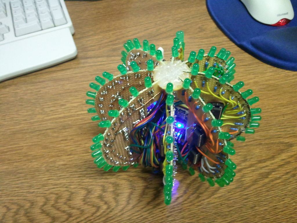
I wanted to thank Nikolai for the inspiration & Null Space Labs HackerSpace for their take on the project. I also wrote Charlie over there to get his input on the spiral animation & he was very nice & helpful. I am going to post all of the code that I used in case anyone is interested. I wouldn’t say that I am the most proficient programmer & am still learning so be kind.
Code:
int clockPin = 13; //IC Pin 11, Yellow Jumper
int dataPin = 11; //IC Pin 14, Blue Jumper
int latchPin = 8; //IC Pin 12, Green Jumper
const int xPin = 2; // X output of the accelerometer
const int yPin = 3; // Y output of the accelerometer
word patterns[176] = {
0b1100000000000000,
0b0110000000000000,
0b0011000000000000,
0b0001100000000000,
0b0000110000000000,
0b0000011000000000,
0b0000001100000000,
0b0000000110000000,
0b0000000011000000,
0b0000000001100000,
0b0000000000110000,
0b0000000000011000,
0b0000000000001100,
0b0000000000000110,
0b0000000000000011,
0b0000000000000001,
0b0000000000000000,
0b0000000000000000,
0b0000000000000000,
0b0000000000000000,
0b0000000000000000,
0b0000000000000000,
0b1010111010001101,
0b0110101010011010,
0b0101010010011100,
0b0000000000000000,
0b0000000000000000,
0b0000000000000000,
0b0000000000000000,
0b0000000000000000,
0b0000000000000000,
0b0000000000000000,
0b0000000000000000,
0b0000000000000000,
0b0000000000000000,
0b0000000000000000,
0b0000000000000000,
0b0000000000000000,
0b0000000000000000,
0b0000000000000000,
0b0000000000000000,
0b0000000000000000,
0b0000000000000000,
0b0000000000000000,
0b0000000000000000,
0b0000000000000000,
0b0000000000000000,
0b0000000000000000,
0b0000000000000000,
0b0000000000000000,
0b0000000000000000,
0b0000000000000000,
0b0000000000000000,
0b0000000000000000,
0b1010111010001101,
0b0110101010011010,
0b0101010010011100,
0b0000000000000000,
0b0000000000000000,
0b0000000000000000,
0b0000000000000000,
0b0000000000000000,
0b0000000000000000,
0b0000000000000000,
0b0000000000000000,
0b0000000000000000,
0b0000000000000000,
0b0000000000000000,
0b0000000000000000,
0b0000000000000000,
0b0000000000000000,
0b0000000000000000,
0b0000000000000000,
0b0000000000000000,
0b0000000000000000,
0b0000000000000000,
0b0000000000000000,
0b0000000000000000,
0b0000000000000000,
0b0000000000000000,
For more detail: Arduino BlinkyBall Project
-
How did the author modify the original design?
The author scaled up the design dimensions and reduced the number of slices because they made their own boards by hand. -
What components make up each slice?
Each slice consists of two 8-bit shift registers, 16 LEDs, and 16 resistors. -
How are the slices assembled into a sphere?
Slices are slid into circular PCBs that have slits cut every 45 degrees using a Dremel tool. -
What provides orientation to the sphere?
A Parallax Mesmic 2125 accelerometer added to the main center board provides orientation. -
How long does it take to charge the battery?
Charging the LiPo battery through the USB mini port takes approximately one hour. -
How long does the battery last during operation?
The battery lasts for approximately 45 minutes after being fully charged. -
Where can I find the code used for this project?
The author posted all the code used in the article text for anyone interested. -
Who inspired the original project mentioned?
The project was inspired by a blog post on hackaday.com featuring a project by Nikolai.
