
Summary of Toaster Oven Reflow Technique
This article details a DIY method for reflow soldering surface-mount printed circuits using a modified toaster oven controlled by an Arduino. It emphasizes safety regarding mains electricity, high temperatures, and leaded solder. The project involves assembling a control circuit with a thermocouple amplifier and solid-state relay to manage the oven's heating profile, which includes specific temperature stages for flux activation, solder melting, and cooling.
Parts used in the Toaster Oven Reflow Project:
- Toaster oven (900W with quartz halogen heaters)
- Arduino (Diecimila or similar)
- Solid-state relay (5A rating)
- K-type thermocouple
- Thermocouple amplifier (AD595 IC1)
- Mains plug patress box
- Electric socket
- Kapton tape
- 100uF capacitor
- Heat-shrink insulation
Introduction
This page describes how to reflow solder surface mount printed circuits using a cheap toaster oven. It owes a great deal to Nophead’s Cooking with Hydraraptor blog post.
The picture shows Sally Bowyer (Director, RepRapPro Ltd) preparing components for soldering in the oven. For more instructions on this see the video at the bottom of this page.
Safety
This uses mains electricity, which will kill you if you touch it. So don’t.
It makes things hot (solder melting temperatures), which will burn you if you touch them. So don’t.
Solder contains lead. Lead is bad for you. Don’t use the oven you use for this for food.
Equipment
The toaster oven we use is this 900W one from Argos in the UK. It costs £25.
Just about any toaster oven will do, as long as its power rating is not too high. The solid-state relay (see below) can switch 5A; power = volts x amps; do the mathematics…
Try to get one with quartz halogen heaters though – these respond very fast to being switched on and off, which is good.
You will also need an Arduino to control it. Just about any Arduino will do; we use the Arduino Diecimila, because we happened to have a few lying about.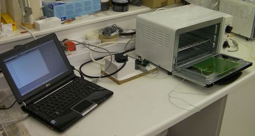 Finally, you need a solid-state relay so the Arduino can turn the oven on and off, and a temperature sensor that will do up to 250oC.
We use this solid-state relay from Farnell, and a K-type thermocouple plus thermocouple amplifier (see below). Alternatively you could use the same types of thermistors that RepRap uses for its extruders as temperature sensors – the temperatures are about the same.
Control
This is the circuit diagram of the thermocouple amplifier. IC1 is an AD595. It needs a Type K thermocouple.
MakerBot sell a kit for the amplifier here.
The thermocouple connects to pins 1 and 14. You can’t solder thermocouple wire, so have a screw connector for those pins.
If you get silly temperatures reported by the firmware (see below) or the warning LED lights, then the thermocouple wires are the wrong way round. Swap them.
JP1 connects to the Arduino:
- JP1 pin 1 -> Arduino +5v.
- JP1 pin 2 -> Arduino A0.
- JP1 pin 3 -> Arduino Ground.
If you get noise problems on the temperature signal, solder a 100uF capacitor between Vcc and ground. Take care to get the capacitor polarity right.
The solid-state relay has four connections. Two go in series with the mains live wire. The other two turn the mains current on and off.
The neatest thing to do with the solid-state relay is to mount it inside a mains plug patress box. You will then have a general-purpose device that will allow you to control any mains load (up to 5A) with the Arduino. Run the control wires out of the side of the box and connect them to the Arduino: + goes to the Arduino LED (D13 on an Arduino Diecimila), the other control connection goes to the Arduino ground.
Note that there is no electrical connection inside the solid-state relay between the control circuit and the mains circuit. The device is optically coupled, so there is no danger that you will get mains flowing through your Arduino (as long as you wire things up right…).
The picture shows the control system, which is all screwed down to a small wood plank.
On the left is the electric socket. This is open so you can see the solid-state relay mounted inside.
Run a mains cable with a plug on the end into the electric socket to power the oven.
Put the relay’s switched side in series with the cable’s live wire on the way to the live terminal of the socket; run the neutral and earth straight through to their socket terminals. Insulate any exposed live connections carefully with heat-shrink. Run two wires from the control pins to the Arduino as described above. Colour code them so you can remember which one is + when the electric socket is put back together.
In the middle is the Arduino, and on the right is the thermocouple amplifier.
Firmware
Here is the Arduino control program. This has an inbuilt temperature vs. time profile that it follows. The basic rules are:
- heat up to 150oC – this is the flux activation temperature
- heat up more slowly to 183oC – this is the solder’s melting point
- heat up faster to 215oC – this is the reflow temperature
- cool
The timings are not too critical, but you don’t want the components to stay at the highest temperature for too long. The highest temperature is set to 215oC, but you will find that this overshoots a bit to 220oC, which is the actual temperature you want.
Operation
Plug the controller into a mains socket that is, for the moment, switched off.
Plug the oven into the controller.
Connect the Arduino to a computer via a USB cable. You can use the terminal emulator in the Arduino development environment to monitor what is going on, or you can use stand-alone programs like Miniterm (Linux) and Hyperterminal (Windows).
Tape the thermocouple to a part of the PCB where it won’t interfere with the components using Kapton tape.
Place the PCB on the shelf in the middle of the oven.
Close the oven door on the thermocouple lead, taking care that there is slack thermocouple lead in the oven so the PCB doesn’t move when you do this.
Hold the reset button on the Arduino down, then turn on the mains power.
Let the reset button go.
The device should cycle through its range of temperatures and solder your board.
The oven won’t cool as fast as the control curve demands, so open the door when the temperature is on its way down and the target temperature drops below 200oC.
Don’t move the PCB until its temperature gets down to around 150oC. If you move it while the solder is still molten the components may shift.
You will find that the temperature lags behind the profile at the start (up to around 100oC), especially for large PCBs. This doesn’t matter; it’s the higher temperatures that are important, and the oven and controller will follow those quite faithfully.
You may want to use a bit of scrap board the very first time you try it, as a test.
If you are doing lots of boards, you can just press the reset button after you put each one in the oven. When each board is finished the controller will keep the oven switched off until you next press reset.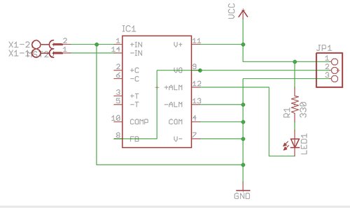
Operation
Plug the controller into a mains socket that is, for the moment, switched off.
Plug the oven into the controller.
Connect the Arduino to a computer via a USB cable. You can use the terminal emulator in the Arduino development environment to monitor what is going on, or you can use stand-alone programs like Miniterm (Linux) and Hyperterminal (Windows).
Tape the thermocouple to a part of the PCB where it won’t interfere with the components using Kapton tape.
Place the PCB on the shelf in the middle of the oven.
Close the oven door on the thermocouple lead, taking care that there is slack thermocouple lead in the oven so the PCB doesn’t move when you do this.
Hold the reset button on the Arduino down, then turn on the mains power.
Let the reset button go.
The device should cycle through its range of temperatures and solder your board.
The oven won’t cool as fast as the control curve demands, so open the door when the temperature is on its way down and the target temperature drops below 200oC.
Don’t move the PCB until its temperature gets down to around 150oC. If you move it while the solder is still molten the components may shift.
You will find that the temperature lags behind the profile at the start (up to around 100oC), especially for large PCBs. This doesn’t matter; it’s the higher temperatures that are important, and the oven and controller will follow those quite faithfully.
You may want to use a bit of scrap board the very first time you try it, as a test.
If you are doing lots of boards, you can just press the reset button after you put each one in the oven. When each board is finished the controller will keep the oven switched off until you next press reset.
For more detail: Toaster Oven Reflow Technique
- What type of toaster oven is best for this project?
A 900W oven with quartz halogen heaters is recommended because they respond very fast to being switched on and off. - How do I prevent electrical danger when wiring the system?
The solid-state relay is optically coupled, ensuring no electrical connection exists between the control circuit and the mains circuit inside the device. - What are the specific temperature targets for the reflow process?
The profile heats to 150C for flux activation, slowly to 183C for the solder melting point, and faster to 215C as the reflow temperature. - Can I use the same oven for cooking food after this project?
No, you must not use the oven for food because it contains lead from the solder. - What should I do if the firmware reports silly temperatures?
If you get silly temperatures reported or the warning LED lights, swap the thermocouple wires as they may be connected the wrong way round. - How can I fix noise problems on the temperature signal?
You can solve noise issues by soldering a 100uF capacitor between Vcc and ground, ensuring correct polarity. - When should I open the oven door during the cooling phase?
You should open the door when the temperature is on its way down and the target temperature drops below 200C. - Why might the temperature lag behind the profile at the start?
The temperature lags behind the profile at the start up to around 100C, especially for large PCBs, but this does not matter as higher temperatures are more important.
