
Summary of Drive with PID Control on an Arduino Mega 2560
This article demonstrates simulating and deploying a simple closed-loop PID control algorithm in Simulink for an Arduino Mega 2560–based four-wheel vehicle. It covers required hardware, building the vehicle and a motor driver using the SN754410 H-bridge, simulating open- and closed-loop models, and running those models on the Arduino. The example uses wheel encoders for feedback and shows how to switch between simulation and hardware execution.
Parts used in the Drive with PID Control on an Arduino Mega 2560:
- Arduino Mega 2560 board
- USB cable
- Texas Instruments SN754410 quadruple high-current half-H driver
- Two 10 kOhm resistors
- Small breadboard
- Breadboard wires
- Mobile platform with four wheels
- Four DC motors
- Two optical encoders (ten-step encoders used in example)
- Battery pack of five AA 1.5V batteries
- Single pole single throw (SPST) switch
This example shows how to simulate a simple closed-loop control algorithm in Simulink and how to run it on an Arduino Mega 2560 board.
Contents
- Introduction
- Prerequisites
- Required Hardware
- Task 1 – Build the Vehicle
- Task 2 – Build the Motor Controller
- Task 3 – Simulate Open-Loop Control Model
- Task 4 – Run Open-Loop Control Model on the Arduino Mega 2560 Board
- Task 5 – Simulate Closed-Loop Control Model
- Task 6 – Run Closed-Loop Control Model on the Arduino Mega 2560 Board
- Other Things to Try
- Summary
Introduction
In a vehicle using independent wheel control, applying the same power to each wheel generally does not result in the vehicle moving straight. This is caused by mechanical and surface differences experienced by each of the wheels. To reduce deviation in the vehicle heading, a better approach is to use a closed-loop controller which adjusts the power applied to two motors based on the difference in their rates of rotation. One such controller is a well-known proportional-integral-derivative (PID) controller.
PID control is a basic control loop feedback mechanism. The controller minimizes the difference between the measured and the desired value of a chosen system variable by adjusting the system control inputs.
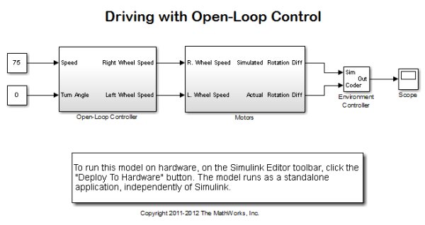
This example shows you how to simulate the controller using a simple plant model, first with no feedback control (Open-Loop Control), and then with feedback control (Closed-Loop Control). This example also illustrates how to switch between simulating the PID controller and running it on hardware in the same model.
Prerequisites
We recommend completing Getting Started with Arduino Mega 2560 Hardware.
Required Hardware
To run this example you will need the following hardware:
Controller board:
- Arduino Mega 2560 board
- USB cable
Motor controller parts:
- Texas Instruments™ SN754410 quadruple high-current half-H driver
- Two 10 kOhm resistors
- Small breadboard
- Breadboard wires
A four-wheel vehicle:
- A mobile platform with four wheels powered by four DC motors
- Two optical encoders wired to front DC motors
- A battery pack consisting of five AA 1.5V batteries
- A single pole, single throw (SPST) switch
Notes:
- This example was tested with the four-wheel vehicle built using DFRobot 4WD Arduino-Compatible Platform w/Encoders.
- Other vehicle kits can be used as long as they have the same mechanical characteristics (four wheels, four DC motors and two encoders).
- With a minor modification to the controller connections, a vehicle with only two DC motors can be used as well.
- Encoders used in this example are ten-step encoders. Different encoders can be used with minor modifications to the example models.
Task 1 – Build the Vehicle
1. Assemble the mobile platform. Attach the two DC motors with encoders to the front wheels.
2. Attach the other two DC motors to the rear wheels. If your platform has only two DC motors, let the rear wheels rotate freely.
3. Assemble the battery pack and attach it to the mobile platform using suitable fasteners.
4. Connect the positive end of the battery pack to the switch using the breadboard wires.
Note: If you are using DFRobot 4WD Arduino-Compatible Platform w/Encoders kit, follow the vendor’s instructions.
Task 2 – Build the Motor Controller
The Arduino Mega 2560 board alone cannot provide high enough current to power DC motors. For that purpose, you will build the motor controller based on the Texas Instruments SN754410 quadruple high-current half-H driver.
1. Assemble the motor controller using the following circuit diagram.
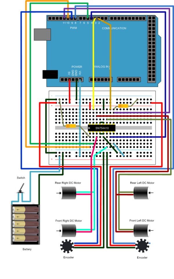
2. Connect the controller to the vehicle battery pack following the same circuit diagram.
For more detail: Drive with PID Control on an Arduino Mega 2560
- What is the purpose of the example?
To show how to simulate a PID closed-loop controller in Simulink and run it on an Arduino Mega 2560 board for a four-wheel vehicle. - What hardware is required to run this example?
Arduino Mega 2560, USB cable, SN754410 driver, two 10 kOhm resistors, breadboard, breadboard wires, four-wheel mobile platform with four DC motors, two optical encoders, five AA battery pack, and an SPST switch. - Why is a motor driver needed with the Arduino Mega 2560?
Because the Arduino cannot provide high enough current to power DC motors directly, so the SN754410 H-bridge driver is used. - Can this example work with vehicle kits other than DFRobot 4WD?
Yes, other vehicle kits can be used as long as they have the same mechanical characteristics (four wheels, four DC motors, and two encoders). - Can a vehicle with only two DC motors be used?
Yes, with a minor modification to the controller connections a two-motor vehicle can be used and rear wheels can rotate freely. - What type of encoders does the example use?
The example uses ten-step optical encoders, though different encoders can be used with minor model modifications. - What tasks are demonstrated in the example?
Building the vehicle, building the motor controller, simulating open-loop and closed-loop models, and running both models on the Arduino Mega 2560. - What is the control objective of the PID controller in this example?
To reduce deviation in vehicle heading by adjusting motor power based on differences in wheel rotation rates.
