
Summary of Basic Arduino Tutorials : 01 Blinking LED
This article guides users through building a basic Arduino circuit to flash an LED with 1-second intervals. It details connecting power cables, a resistor, and control wires to a breadboard, attaching the LED correctly by pin length, and linking the board to a computer for code upload. The project serves as a foundational step for more complex electronics.
Parts used in the Blinking LED Circuit:
- 1 x LED
- 3 x Cables
- 1 x 330 Ω Resistor
- 1 x Arduino board (UNO used)
- 1 x USB cable
- 1 x Computer with Arduino software installed
- 1 x Breadboard
- Breadboard/Circuit-board Holder (Optional)
In this instructable, I’m going to show you how to make a simple circuit/code with an arduino, which will make an LED connected to it flash from off to on, with 1-second intervals, as shown below.
This is a very easy, basic idea, however it leads to many more complicated codes and circuits.
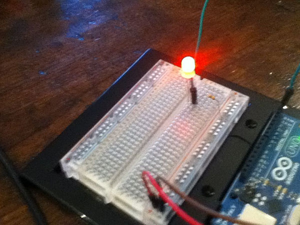
Attaching the Power Cables and resistor to the Breadboard
Firstly you will need to plug one end of a wire into the ‘5v’ Power output on the arduino, and the other end into the positive section of the breadboard.
Then you need to plug one end of a wire into the ground (‘GND’) Power output, and the other end into the Negative section of the Breadboard.
Finally, you need to plug one end of the resistor from the Negative section of the Breadboard, to any horizontal line on the main section. (NOTE- It is very important to use AT LEAST a 330 ohm resistor with this circuit. If you don’t, then you will almost certainly blow the LED.)
Attach the control wire to the Breadboard
Step 4: Attaching Led
Now to attach the Led into the circuit. Be warned, it will NOT do anything until you have uploaded the code to the board, which is done at a later stage.
the way this is done is to put it so that each pin is next to a wire/resistor. This sounds unclear, but pictures should help
You have to put the LONGER pin next to the wire connected to the port, and the shorter pin next to the resistor.
Plug into computer.
Now you need to plug the arduino board into the computer. Nothing really to say here, just make sure that you don’t break anything!
3 x Cables
1 x 330 Ω Resistor
1 x Arduino board (it can be any kind, but for this instructable i used the UNO board).
1 x USB cable
1 x Computer with Arduino software installed (http://www.arduino.cc/en/Main/software if you haven’t already got it)
1 x Breadboard
Optional
Breadboard/Circuit-board Holder.
For more detail: Basic Arduino Tutorials : 01 Blinking LED
-
What is the minimum resistance required for this circuit?
You must use at least a 330 ohm resistor; otherwise, you will almost certainly blow the LED. -
How do I connect the power cables to the breadboard?
Plug one wire from the '5v' output to the positive section and another from the 'GND' output to the negative section of the breadboard. -
Which pin of the LED connects to the digital port wire?
The longer pin of the LED must be placed next to the wire connected to the port. -
Why does my LED not light up immediately after assembly?
The LED will not do anything until you have uploaded the code to the board. -
Can I use any type of Arduino board for this project?
Yes, the article states that it can be any kind of Arduino board, though the UNO was used for this instructable. -
Where should the shorter pin of the LED be placed?
The shorter pin should be placed next to the resistor. -
What software is needed to run this project?
You need a computer with Arduino software installed, available at arduino.cc.
