
Summary of Medicine Safe
This article details a DIY automated medicine safe project for school, featuring RFID access control, an LCD interface, and a servo-driven locking mechanism. The build involves assembling 3D-printed structural components alongside electronic modules like an Arduino Uno and buzzer to create a secure storage unit with button controls and digital display.
Parts used in the Medicine Safe:
- 1x 14 lock pin sleeve large
- 1x 15 lock pin sleeve small
- 1x 17 lock counter pin
- 1x 18 pin shooter
- 14x 19 tray shelf
- 4x 22 leg mounting corners
- 4x 22.1 mounting brackets instead of bolts
- 4x 23 mounting brackets 3 sides
- 2x 24 fixing corners 2 sides
- 1x 27 servo arm
- 3x 26.2 hinge 0.2mm clearance (or 26 hinge 0.2mm clearance)
- 1x 25 door handle
- 1x 16 slot servo holder
- 1x 20 tray partition (up to 35 units)
- 1x rfid-RC522 + batch/card
- 1x arduino uno
- 1x Servo SG90
- 1x 1602 LCD I2C
- 1x buzzor
- 4X buttons (14x20 round hole 12mm)
- 1x ac/dc adapter (6v)
- 1x breadboard
We created this project for MSReva as an assignment from school.
Supplies
Laser or print all parts (see githup):
4x: 22.1 mounting brackets instead of bolts
4x 23 mounting brackets 3 sides
3x: 26.2 hinge 0.2mm clearance or 26 hinge 0.2mm clearance
(If your printer is very accurate the 0.2mm would not be a problem, if you want to be sure use the 0.3mm.)
Lasered parts(3mm thickness plate):
20 tray partition: you can choose how many times you lazer it, it comes between the trays as a partition, you can lazer a total of 7×5(35).
parts:
1X: rfid-RC522 + batch/card
1X: arduino uno
1X: Servo SG90
1X: 1602 LCD I2C
1X: buzzor
4X buttons (14×20 round hole 12mm)
1x ac/dc adapter (6v)
Cables
1x breadboard (You can also make it without, but only makes it easier.)
Step 1: The Start of the Built
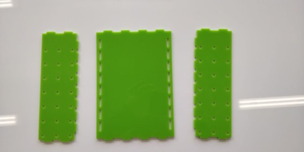
Make sure you arrange the inside back plate and inner side plate as on the picture above.
Step 2:
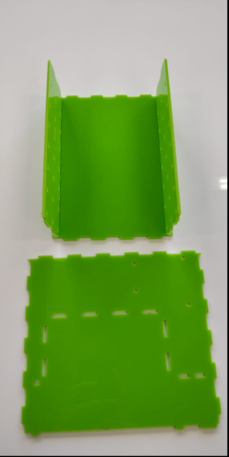
Build the plates together as shown above and search the bottom plate.
Step 3:
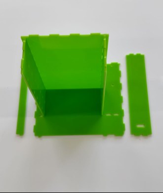
Put the construction on the base plate and search the cover plates.
Step 4:
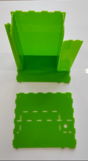
Connect the cover plates as shown above and search the top plate.
Step 5:
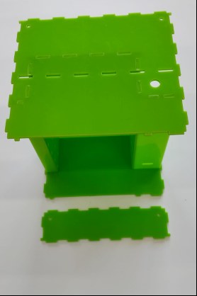
Connect now the top plate and search the back plate LCD.
Step 6:
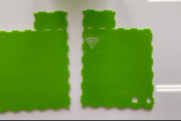
Put the plate on top of the construction and search the side plate and the side plate with RFID.
Step 7:
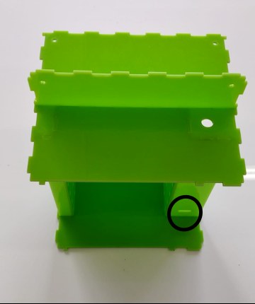
You connect the cables from the RFID(on the IRQ comes no cable) to the Arduino, through the provided hole. You can find the electrical diagram here and above, you screw it on with m3 nuts on the inside and bolts on the outside and place the RFID inside.
Step 8:
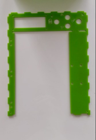
Place the side plates as shown below. Make sure the plate with the logo is placed on the right.
Search the front plate.
Step 9: Starting With the Door
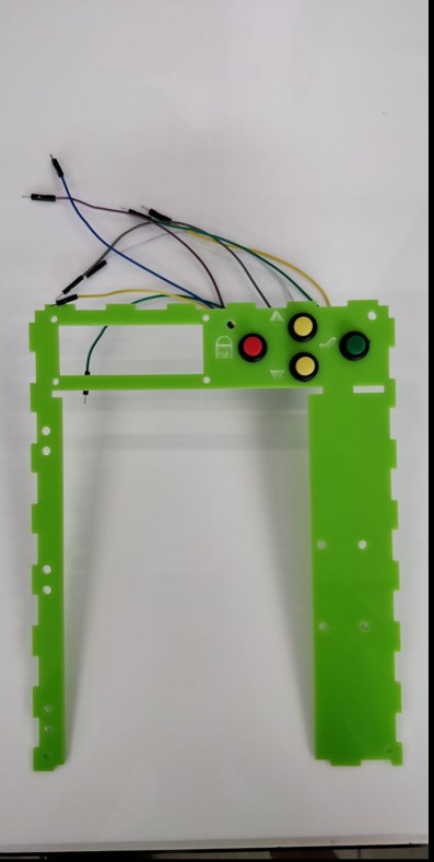
Place the 4 buttons (14x20mm, hole 12mm), You can adapt the size of the holes if you want to use your own (github.) and solder the wires to the buttons and place it into the front plate.
Step 10: LCD
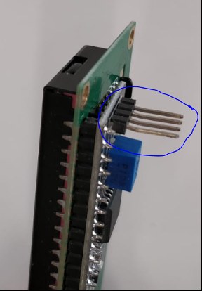
Take the LCD and bend the headers as shown in the picture above.
Place the LCD in the rectangle (fix it with the M3 nuts and bolts and spacers so that the lcd is straight and flush with the front plate).
Step 11: Lock
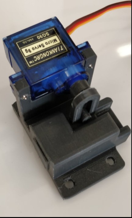
Build the construction as showen above with the servo, servo arm, servo slot holder and pin. First screw the arm to the servo, then insert the pin into the holder and place the servo with the arm through the protruding loop. Fix the servo with screws.
This will be used as lock. Make sure the servo is at 90 degrees.
Step 12:
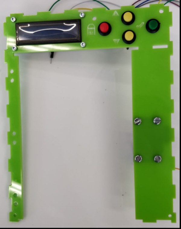
Place the lock on the 4 holes of the front plate and fix it with 4 M4 bolts and nuts.
Step 13:
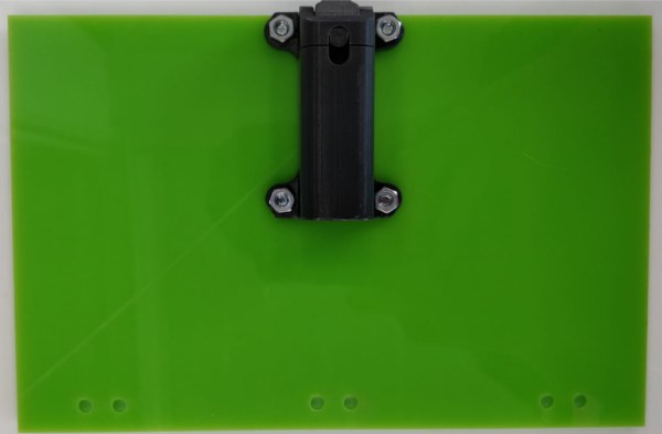
Now find the door plate, door handle, pin sleeve small/large, shooter pin and a spring. Mount the small pin sleeve and the doorknob to the outer holes, but on opposite sides (make sure the slanted side of the sleeve is on the outside, with M4 bolts and nuts). Insert the spring into the large sleeve and then the striker pin with the beveled side out and the protruding cylinder into the slot of the sleeve. Mount the large sleeve to the middle 2 of the door on the same side as the small sleeve (put the shooter into the small sleeve as well, also with M4 bolts and nuts).
Step 14:
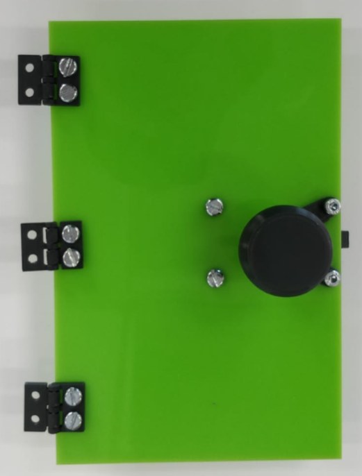
Find the hinges and mount them to the door with M4 bolts and nuts (place the hinges on the outside of the door (make sure the button of the hinge is pointing outwards).
Step 15:
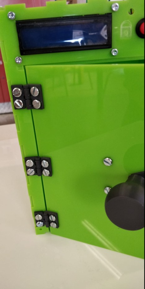
Now mount the remaining mounting points of the hinges to the front plate also with M4 bolts and nuts.
Source: Medicine Safe
-
What is the primary function of this project?
The project is an automated medicine safe created as a school assignment that uses RFID access, an LCD display, and a servo lock. -
How many tray shelves are required for the build?
You need 14 units of part 19 tray shelf for the construction. -
Can I use different clearance sizes for the hinges?
Yes, you can use 26.2 hinge 0.2mm clearance or 26 hinge 0.2mm clearance; if your printer is very accurate, 0.2mm works, otherwise use 0.3mm. -
How should the RFID module be connected to the Arduino?
You connect cables from the RFID to the Arduino through a provided hole, noting that no cable goes to the IRQ pin. -
What size holes are needed for the buttons?
The instructions specify using 4 buttons with 14x20 dimensions and a 12mm round hole, though these can be adapted. -
At what angle must the servo be positioned during installation?
The servo must be fixed at 90 degrees when building the lock mechanism. -
Which side should the logo plate be placed on?
The side plate with the logo must be placed on the right side during assembly. -
How is the door handle mounted relative to the pin sleeves?
The doorknob is mounted to the outer holes on opposite sides from the small pin sleeve. -
What fasteners are used to secure the lock to the front plate?
The lock is fixed to the four holes of the front plate using 4 M4 bolts and nuts.
