Summary of DIY ESP32 Security CAM
Summary: This article describes a DIY ESP32 CAM security camera powered by a reverse-engineered 5V charger circuit on a custom PCB, placed in a 3D-printed enclosure. The builder flashes the AI-Thinker ESP32-CAM with the CameraWebServer sketch, assembles the PCB (SMT reflow and THT parts), and uses either the replicated charger or an isolated 5V SMPS module. The camera streams video over Wi-Fi via its IP address as a low-cost alternative to commercial Wi-Fi security cameras.
Parts used in the DIY ESP32 Security CAM:
- ESP32-CAM (AI-Thinker)
- Custom PCB (designed in OrCAD, manufactured by PCBWay)
- 3D printed enclosure (PLA)
- Charger circuit (reverse-engineered 5V 1A charger schematic)
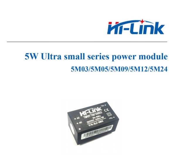
- Isolated 5V 1A SMPS module (optional pads provided on PCB)
- AC power cord
- Female header pins for ESP32 connection
- FTDI USB-to-Serial programming module
- THT components: capacitors, fuse, MOV, transformer
- Solder paste (or stencil alternative)
- DIY SMT hotplate for reflow
- Acrylic transparent sheet (front window)
Hey guys and welcome back,
This is my DIY Security Cam which is made from an ESP32 connected with a 5V Charger circuit that converts 240V AC into 5V DC for ESP32 to run.
The goal for making this project was to make a cheaper alternative to the existing WIFI Security Camera.
Also, huge thanks to PCBWay for Supporting this project, Check out PCBWay for getting great PCB Service at a relatively less cost.
Supplies
These are the things that I’ve used in this project-
- ESP32 CAM
- Custom PCB (which was provided by PCBWay)
- 3D Printed Enclosure
- Charger Circuit (BOM is attached)
- Isolated 5V 1A SMPS Module
Step 1: Getting Started
Now, a few weeks ago I a post about the ESP32 CAM which you can check out, https://www.instructables.com/ESP32-CAM-WEB-Server-and-Getting-Started-Guide/
In that post, we learn how to control the ESP32 CAM and flash it with a UART Module. Flashing this esp32 is a pretty easy process, we first connect the module in the right writing order and then connect this with Arduino IDE and follow some basic guidelines like we need to press the Reset button once while uploading the sketch and our esp32 cam will flash like a normal esp32.
Here we have an ESP32 that contains the CAM webserver sketch that enables us to connect this it with the internet and see the live camera footage.
doesn’t that sound like a security camera?
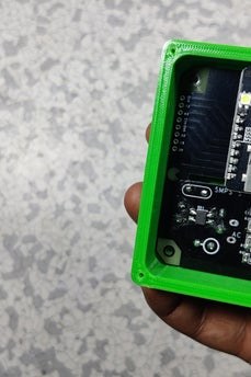
yes it does, the wifi security cam do exactly this but they provide more features that are mostly software-based so what I’m gonna do here is, I will provide this esp32 power with a charger circuit, I will use a custom PCB in this project which will contain the esp32 and charger circuit and then I will put that custom PCB in a 3D Printed enclosure.
this is the plan.
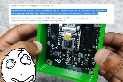
well, it will work electronically but I’m not pretty sure that the PLA can withstand being outside for this kind of project.
Step 2: Circuitry
Anyways, to get started with this project, I first designed a charger circuit by replicating and reverse engineering an existing 5V 1A Charger circuit that I found in an existing commercial mobile phone charger. (SCHEMATIC IS ATTACHED)
Now, this project involves working with the AC supply which is pretty lethal so I don’t recommend you guys to replicate this project as I did, instead of making an SMPS CIrcuit, you can use an isolated power supply module to power this board. it’s still dangerous but it will decrease the chances of getting elecuted by this project.
To use the isolated power supply, I have already added its Pads on the PCB so we can just solder this onto the circuit or use an extremely dangerous non-isolated charger circuit.
I designed this whole project in my OrCAD software, I wanted to add a custom silkscreen to this board so I prepared this image in GIMP and then exported the PNG image.
then I converted the PNG file into a BMP (because the OrCAD only imports BMP Images) and then added this image onto my PCB design and this was the result! note- this method will be different for every PCB Designing suit so just follow your PCB Cad software image importing process and you’ll be good.
Step 3: Getting PCB Made From PCBWay
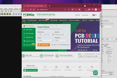
After finalizing the PCB, I exported its Gerber data ad send that to PCBWay for samples,
I received the PCBs in a week, PCB quilty was pretty great and I’m happy with it. PCBWay you guys rock, Check out PCBWay for getting great PCB Service at less cost!
Step 4: Assembly Process
After receiving the PCBs, I started the assembly process of this board.
- We first add solder paste to each component’s pad one by one. (a better alternative is to use a stencil which I didn’t get because I’m such a genius )
- After this, I added components to their assigned place one by one in the right order and then after doing that, I verify the board one last time, and then I put the whole circuit onto my DIY SMT Hotplate for the reflow process.
- Solder paste will melt as soon as the reflow surface hit the solder paste melting temp and then we carefully remove the PCB from the hotplate and let it cool down for a little bit.
- after checking the PCB solder joints and making sure that we didn’t short any components, we then move on to the next step which is to add THT components like the capacitors, fuse, MOV, and transformer.
- After adding these components, I added a female header pin to connect esp32 with this board, and our circuit is finally ready for its first test.
but before that, I added the circuit on ts 3D Printed body and then added an AC Cord to the input of the PCB to supply 240V AC t this setup.
Step 5: Flashing ESP32 CAM Quick Look
CHeckout the previous Post for a full walkthrough.
https://www.instructables.com/ESP32-CAM-WEB-Server…
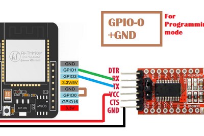
ESP32 CAM doesn’t have an onboard programming chip which is a bummer, because of this we have to add an external USB to the Serial Programming module.
For That, I will be using an FTDI USB to Serial module.
Follow the following Wiring arrangement to hook FTDI Module with ESP32 CAM.
- Set FTDI output to 5V
- Connect the FTDI’s VCC (which is 5V) to 5V of ESP32 CAM
- GND to GND
- RX to U0T
- TX to U0R
- GPIO0 which is IO0 to GND (this will put the ESP32 CAM in Flash Mode)
Before Flashing Process, you need to change few things in the example sketch.
- Go to Example> ESP32> Camera and open the CameraWebServer sketch
- Input your SSID and password
- Change the camera module from #define CAMERA_MODEL_WROVER_KIT to #define CAMERA_MODEL_AI_THINKERNow,
- Go to Tools and select the right board which is in our case AI-Thinker ESP32-CAM.
- Select the right port and hit upload.
Now, when the ESP32 Starts its uploading process you will see the connecting message with dots and dashes. press the reset button on the bottom side of the board when dots and dashes start.
If you have encountered an error during this setup that says unable to connect, this means your timing was not good, try again and when the first dot appears in the debugging menu, long-press the reset button for at least 1 second. After few seconds, your sketch will be uploaded.
- now plug out the USB from FTDI Module and remove the jumper between GPIO0 and GND.
- plug in the USB and open up the serial monitor.
- ESP32 will get connected with WIFI (which would take 1min) and you will see the IP address of the ESP32 CAM.
Step 6: 3D Printed Enclosure
I prepared its body in fusion 360 and then 3D Printed it with PLA, yes I know, I should’ve used a better material that can withstand the outside heat as PLA will start deforming at 160°C, and here at my place, the outside temp is around 35-40 outside so the PLA might melt and that’s one flaw.
well, that’s a gamble that I took so maybe it will not melt, we will see how that goes. I’ve already flashed the ESP32 with the ESP32 CAM webserver sketch and I already have its IP address.
https://www.instructables.com/ESP32-CAM-WEB-Server-and-Getting-Started-Guide/
so we just need to make sure first that the ESP32 is fed with a 5V supply and for that, I checked the Voltage on ESP32’s VCC and GND Port.
Now, at last, I added this acrylic transparent sheet on the first side of the enclosure with screws and hot glue, hot glue will create a gasket in between the acrylic transparent sheet and 3D Printed Body which will hopefully protect the inside from moisture content.
Step 7: RESULT
After finalizing this whole project, I placed oy outside my room and plugged the AC Supply into it.
To monitor the live feed, we can just go to the ESP32 CAM IP address and view the live feed.
And that is how you can save so many bucks or rupees in my case by not purchase an actual security cam and DIY this whole thing for less than 15$ or 1100 Rupees. Leave a comment if you need any help with this project!
Source: DIY ESP32 Security CAM
- What is the main purpose of this DIY ESP32 Security CAM?
To create a cheaper alternative to existing Wi-Fi security cameras by using an ESP32-CAM on a custom PCB with a 5V charger circuit and 3D-printed enclosure. - Can I use an isolated power supply instead of the charger circuit?
Yes, the article recommends using an isolated power supply module and provides pads on the PCB for it to reduce electrocution risk. - How do I program the ESP32-CAM for this project?
Use an FTDI USB-to-Serial module set to 5V, wire VCC, GND, RX, TX, and pull GPIO0 to GND for flash mode, then upload the CameraWebServer sketch from Examples after setting SSID, password, and camera model to AI_THINKER. - Does the ESP32-CAM have an onboard USB programming chip?
No, the ESP32-CAM lacks an onboard programming chip, so an external USB-to-serial module like FTDI is required. - What assembly process is used for the custom PCB?
The process uses solder paste (or stencil), place components in order, reflow on a DIY SMT hotplate, then add THT components and headers. - How do I view the live camera feed?
After flashing and connecting to Wi-Fi, open the ESP32-CAM IP address in a browser to view the live feed. - Will PLA enclosure withstand outdoor use?
The article notes concern that PLA may deform in outdoor heat and may not be reliable long-term. - What should I change in the example sketch before uploading?
Input your SSID and password and change the camera model directive to CAMERA_MODEL_AI_THINKER. - What if flashing fails due to connection timing?
Try again and when the first dot appears in the debug console, long-press the reset button for at least one second to improve timing. - How much did the DIY project cost according to the article?
The builder states the project cost under 15 USD or about 1100 Rupees.