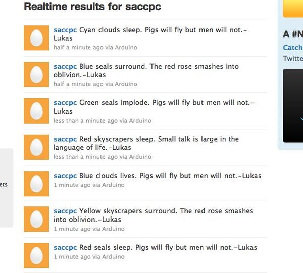
This is a project that was inspired by Marc de Vinck’s Kitty Twitty Cat Toy http://makezine.com/22/kittytwitty/ . It incorporates an RFID reader and the BlinkM, a programable RGB LED. The lamp tweets random colored poems when it detects one of the three RFID cards which each represent one of the primary colors of light. These colors can be mixed allowing you to make seven different colors of poems. An example red poem is “Red sirens see. Clocks make a good bed.”
Included are two versions of the same project. One version used the Seeed Studio 125Khz RFID module, while the other used the The Parallax Serial RFID Reader / Writer Module
Twitter Lamp from SACC-PC on Vimeo.
Step 1: Parts
Major Components in Project
Seeed Version Part List
* Seeed Studio 125Khz RFID module – Wiegand (RFR102A1M) http://www.seeedstudio.com/depot/125khz-rfid-module-wiegand-p-225.html?cPath=144_153
* 3 RFID 54mm x 85mm Rectangle Tags-http://www.parallax.com/Store/Accessories/CommunicationRF/tabid/161/ProductID/689/List/0/Default.aspx?SortField=ProductName,ProductName
*1 BlinkM http://thingm.com/products/blinkm
* 1 Arduino
* 1 Arduino Ethernet Shield-http://www.adafruit.com/index.php?main_page=product_info&products_id=83&zenid=9b755efcfe260b30eee32576599c81c5
* WIZ812MJ Ethernet SPI/Bus Module (RJ45) 2.54mm Pitch http://www.saelig.com/product/ETH042.htm
* 1 Ethernet Cable
* 1 USB Cable
* 1 Unused Ethernet Port with connection to internet
* 1 Solderless Breadboard
* 1 LED
* 1 220Ω resistor
* 22 AWG solid core wire
* Soldering Iron
* Lead-Free Solder
* Wire Strippers
* Wire Cutters
* Glue Gun
* Velum
* Tape
* Hot glue
* Box
* X-acto knife
* Drill
Parallax Version
* The Parallax Serial RFID Reader / Writer Module http://www.parallax.com/Store/Accessories/CommunicationRF/tabid/161/ProductID/688/List/0/Default.aspx?SortField=ProductName,ProductName
* 3 RFID 54mm x 85mm Rectangle Tags-http://www.parallax.com/Store/Accessories/CommunicationRF/tabid/161/ProductID/689/List/0/Default.aspx?SortField=ProductName,ProductName
* 1 BlinkM-http://thingm.com/products/blinkm
* 1 Arduino
* 1 Arduino Ethernet Shield-http://www.sparkfun.com/products/9026
* 1 Ethernet Cable
* 1 USB Cable
* 1 Unused Ethernet Port with connection to internet
* 1 Solderless Breadboard
* 22awg solid core wire
* Soldering Iron
* Lead-Free Solder
* Wire Strippers
* Wire Cutters
* Glue Gun
* Velum
* Tape
* Hot glue
* Box
* X-acto knife
* Drill
* Cardboard Tube[/box]
Step 2: Seeed RFID
The RDM 125KHz card mini-module is designed for reading code from 125KHz/ 134.2KHz card compatible read-only tags and read/write card . It can be applied in office/home security, personal identification, access control, anti-forgery, interactive toy and production control systems etc.
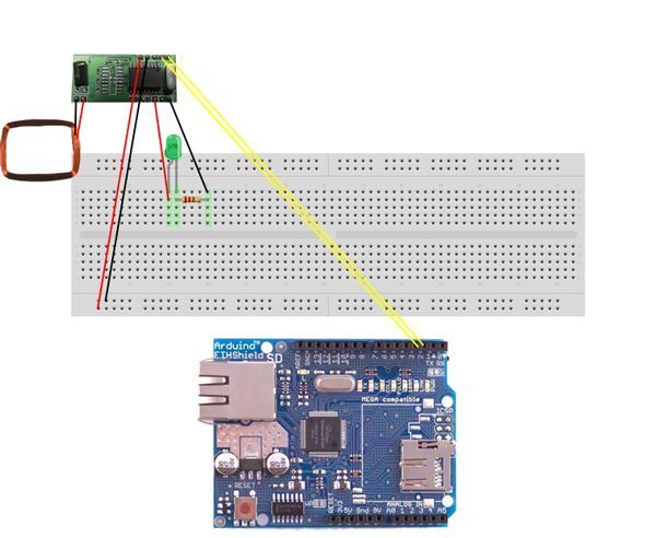
1. To connect the RFID reader to the Arduino, attach pins 1 and 2 of the RFID reader to digital pins 2 and 3. Connect the RFID reader to 5V and ground.
2. Attach the LED and the 220Ω resistor to the RFID reader. The LED will serve as a signal indicator.
3. Upload this code to your Arduino:
/* Modified from
* Crazy People
* By Mike Cook April 2009
* An RFID reader outputting 26 bit Wiegand code to pins:-
* Reader attached to Pins 2 & 3
* Interrupt service routine gathers Wiegand pulses (zero or one) until 26 have been received
* Then a string is sent to Serial
*/

volatile long reader1 = 0;
volatile int reader1Count = 0;

void reader1One(void) {
reader1Count++;
reader1 = reader1 << 1;
reader1 |= 1;
}

void reader1Zero(void) {
reader1Count++;
reader1 = reader1 << 1;
}

void setup()
{
Serial.begin(9600);
// Attach pin change interrupt service routines from the Wiegand RFID readers
attachInterrupt(0, reader1Zero, RISING);//DATA0 to pin 2
attachInterrupt(1, reader1One, RISING); //DATA1 to pin 3
delay(10);
// the interrupt in the Atmel processor misses out the first negitave pulse as the inputs are already high,
// so this gives a pulse to the reader input line to get the interrupts working properly.
// Then clear out the reader variables.
// The readers are open collector sitting normally at a one so this is OK
for(int i = 2; i<4; i++){
pinMode(i, OUTPUT);
digitalWrite(i, HIGH); // enable internal pull up causing a one
digitalWrite(i, LOW); // disable internal pull up causing zero and thus an interrupt
pinMode(i, INPUT);
digitalWrite(i, HIGH); // enable internal pull up
}
delay(10);
// put the reader input variables to zero
reader1 = 0;
reader1Count = 0;
}

void loop() {
if(reader1Count >=26){
int serialNumber=(reader1 >> 1) & 0x3fff;
int siteCode= (reader1 >> 17) & 0x3ff;

Serial.print(" Reader 1:");
Serial.print(reader1,HEX);
Serial.print(" ");
Serial.print("Reader 1 converted to DEC:");
Serial.print(reader1& 0xfffffff);
Serial.print(" ");
Serial.print("siteCode:");
Serial.print(siteCode);
Serial.print(" ");
Serial.print("serial number:");
Serial.println(serialNumber);

reader1 = 0;
reader1Count = 0;
}
}
4.Open the Serial monitor and record the numbers that the serial monitor spits out when you wave your RFID card in front of the RFID antenna.
Step 3: Seeed and BlinkM
1. Connect the BlinkM d pin (the data pin) to the analog 4 of the Arduino.
2. Connect the BlinkM c pin (the clock pin) to analog 5 of the Arduino.
3. Connect the BlinkM to 5V and GND.
4. Download the BlinkM_funcs.h file-http://todbot.com/blinkm/example_code/BlinkMTester/BlinkM_funcs.h
5. Create a new sketch.
6. Create a new tab and name it BlinkM_funcs.h
7. Paste in the BlinkM_funcs.h code in the new tab
8. Paste the following code in the main sketch, compile and upload. The code allows the user to control the BlinkM with the RFID tags:
#include <Wire.h>
#include "BlinkM_funcs.h"

volatile long reader1 = 0;
volatile int reader1Count = 0;

#define blue [your id tag # here]
#define red [your id tag # here]
#define green [your id tag # here]

long prevTime;
int card1;
int card2;
int count=0;

long dec;
int color;

byte r,g,b;

byte addr = 0x09;

void reader1One(void) {
reader1Count++;
reader1 = reader1 << 1;
reader1 |= 1;
}

void reader1Zero(void) {
reader1Count++;
reader1 = reader1 << 1;
}

void setup(){
BlinkM_beginWithPower();
Serial.begin(9600);

// Attach pin change interrupt service routines from the Wiegand RFID readers
attachInterrupt(0, reader1Zero, RISING);//DATA0 to pin 2
attachInterrupt(1, reader1One, RISING); //DATA1 to pin 3
delay(10);

// the interrupt in the Atmel processor misses out the first negitave pulse as the inputs are already high,
// so this gives a pulse to the reader input line to get the interrupts working properly.
// Then clear out the reader variables.
// The readers are open collector sitting normally at a one so this is OK
for(int i = 2; i<4; i++){
pinMode(i, OUTPUT);

// enable internal pull up causing a one
digitalWrite(i, HIGH);

// disable internal pull up causing zero and thus an interrupt
digitalWrite(i, LOW);

pinMode(i, INPUT);
digitalWrite(i, HIGH); // enable internal pull up
}

delay(10);

// put the reader input variables to zero
reader1 = 0;
reader1Count = 0;
}

void loop() {
readCard();
}

void readCard(){
if(count<2){
if(reader1Count >=26){
int serialNumber=(reader1 >> 1) & 0x3fff;
int siteCode= (reader1 >> 17) & 0x3ff;
dec = (reader1& 0xfffffff);
if(count==0){
r=0;
b=0;
g=0;
}
Serial.print("dec=");
Serial.println(dec);

switch(dec){
case red:
r=255;
break;

case green:
g=255;
break;

case blue:
b=255;
break;

default:
color=0;

Serial.print("new tag");
Serial.print(reader1& 0xfffffff);
}

displayColor();
reader1 = 0;
reader1Count = 0;
}else if(reader1Count == 0){
displayColor();
}

if(millis()-prevTime>2000){
count++;
prevTime=millis();
}
}else{
count=0;
}
}

void displayColor(){
BlinkM_fadeToRGB(addr,r,g,b);
}
Step 4: Seeed and Twitter
1. Cut out holes for the USB and Ethernet and maybe a hole for the power jack if you want to power the arduino that way.
2. Create a 2.5in by 2.5in by 2.5in box of velum with the 2.5in by 5in bottom open
3. Tape the vellum to the top of your box over the BlinkM and secure all the parts
4. Download the TrueRandom http://code.google.com/p/tinkerit/wiki/TrueRandom,
NewSoftSerial http://arduiniana.org/libraries/newsoftserial/,
and Twitter http://www.arduino.cc/playground/Code/TwitterLibrary libraries
5. Upload this code to your Arduino
#include <TrueRandom.h>

#include <SPI.h>

#include <avr/pgmspace.h>

#include <Wire.h>

#include <BlinkM_funcs.h>

#include <Client.h>

#include <Ethernet.h>

#include <Server.h>

#include <Udp.h>

#include <EthernetDNS.h>

#include <Twitter.h>

/*
based on Kittty Twitty Cat Toy v1.0
by Marc de Vinck
Jan 6, 2010
KittyTwitty cat toy project found in MAKE, Volume 22

String (formerly TextString) Library by Tom Igoe
http://www.arduino.cc/en/Tutorial/TextString
*/

// the push button
#define pushBtn 6

boolean printed=true;

int color;

volatile long reader1 = 0;
volatile int reader1Count = 0;

#define blue 57337134
#define red 23773468
#define green 23805695

long prevTime;
int card1;
int card2;
int count=0;

long dec;

int r = 0;
int g = 0;
int b=0;

#define addr 0x09

// used to store the status of pin (6)
int var;

long randNum1;
long randNum2;
long randNum3;
long randNum4;

String dataString;
long prevtime = -30000;

// defining the network setting for the Ethernet Shield

// this can be made up
byte mac[] = {
0x1A, 0x6F, 0x99, 0xCD, 0xFF, 0xFF };

//get this from Settings, then change last byte
byte ip[] = {
10,0,1,197 };

//to get token: http://arduino-tweet.appspot.com/
Twitter twitter("[your_token_here]");

prog_char words1_0[] PROGMEM = "Red ";
prog_char words1_1[] PROGMEM = "Green ";
prog_char words1_2[] PROGMEM = "Blue ";
prog_char words1_3[] PROGMEM = "Yellow ";
prog_char words1_4[] PROGMEM = "Purple ";
prog_char words1_5[] PROGMEM = "Cyan ";
prog_char words1_6[] PROGMEM = "White ";

prog_char words2_0[] PROGMEM = "lights ";
prog_char words2_1[] PROGMEM = "arts ";
prog_char words2_2[] PROGMEM = "gases ";
prog_char words2_3[] PROGMEM = "circles ";
prog_char words2_4[] PROGMEM = "needles ";
prog_char words2_5[] PROGMEM = "doorknobs ";
prog_char words2_6[] PROGMEM = "sirens ";

prog_char words3_0[] PROGMEM = "sleep. ";
prog_char words3_1[] PROGMEM = "walk. ";
prog_char words3_2[] PROGMEM = "live. ";
prog_char words3_3[] PROGMEM = "exist. ";
prog_char words3_4[] PROGMEM = "perceive. ";
prog_char words3_5[] PROGMEM = "think. ";
prog_char words3_6[] PROGMEM = "see. ";

prog_char words4_0[] PROGMEM = "Cats are awesome.";
prog_char words4_1[] PROGMEM = "Quilts taste like gingerbread.";
prog_char words4_2[] PROGMEM = "Metal is highly interactive.";
prog_char words4_3[] PROGMEM = "Light is radiation.";
prog_char words4_4[] PROGMEM = "Sound is the wind.";
prog_char words4_5[] PROGMEM = "Clocks make a good bed.";
prog_char words4_6[] PROGMEM = "Glass is opaque.";

PROGMEM const char *words1_table[] ={
words1_0,
words1_1,
words1_2,
words1_3,
words1_4,
words1_5,
words1_6};

PROGMEM const char *words2_table[]={
words2_0,words2_1,words2_2,words2_3,words2_4,words2_5,words2_6};

PROGMEM const char *words3_table[]={
words3_0,words3_1,words3_2,words3_3,words3_4,words3_5,words3_6};

PROGMEM const char *words4_table[]={
words4_0,words4_1,words4_2,words4_3,words4_4,words4_5,words4_6};

char words1_buffer[7];
char words2_buffer[10];
char words3_buffer[10];
char words4_buffer[30];

void reader1One(void) {
reader1Count++;
reader1 = reader1 << 1;
reader1 |= 1;
}

void reader1Zero(void) {
reader1Count++;
reader1 = reader1 << 1;
}

void setup(){
// run this code once
BlinkM_beginWithPower();

//defining the btn as an input so we can read it
pinMode(pushBtn, INPUT);

// starts serial communications so you can debug easier
Serial.begin(9600);

//DATA0 to pin 2
attachInterrupt(0, reader1Zero, RISING);

//DATA1 to pin 3
attachInterrupt(1, reader1One, RISING);

for(int i = 2; i<4; i++){
pinMode(i, OUTPUT);
digitalWrite(i, HIGH); // enable internal pull up causing a one
digitalWrite(i, LOW); // disable internal pull up causing zero and thus an interrupt
pinMode(i, INPUT);
digitalWrite(i, HIGH); // enable internal pull up
}

reader1 = 0;
reader1Count = 0;

//begins the Ethernet connection from the stored information
Ethernet.begin(mac, ip);

connectToTwitter();

Serial.println("Waiting"); // print, used for debugging
}
void connectToTwitter(){
// print a blank line, used for debugging
Serial.println("Connecting to Twitter..."); // print, used for debugging

char testFN1[4]={int(random(4000,5000)) };

if (twitter.post(testFN1)) { // Twitter that we are up and running
int status = twitter.wait(&Serial); // wait for a response from twitter
if (status == 200) { // if Twitter responds 200
Serial.println("Tweet OK!"); // print success // print a blank line, used for debugging

}else {
Serial.print("Tweet failed : code ");
Serial.println(status); // print error code
connectToTwitter(); // print a blank line, used for debugging
}
}else {
Serial.println("connection failed.");
connectToTwitter();
}
}

void loop(){
// run over and over, never stop
readCard();
displayColor();

// check status of wire sensor
checkState();
}
void getString(){
//concatenates poem
dataString= strcpy_P(words1_buffer, (char*)pgm_read_word(&(words1_table[color])));
dataString=dataString+ strcpy_P(words2_buffer,   (char*)pgm_read_word(&(words2_table[int(randNum2)])));

dataString=dataString+ strcpy_P(words3_buffer, (char*)pgm_read_word(&(words3_table[int(randNum3)])));

dataString=dataString+ strcpy_P(words4_buffer, (char*)pgm_read_word(&(words4_table[int(randNum4)])));

dataString=dataString+ " - 1000000000";
}
void tweet(){
// function tweet, this is called if status = 1
char filename[88];

dataString.toCharArray(filename, 88);

Serial.println("Connecting to Twitter..."); // print, used for debugging
Serial.println(); // print a blank line, used for debugging
if (twitter.post(filename)) {
// tweet the completed datastring of words
Serial.print("Tweeting -- "); // print, used for debugging
Serial.println(dataString); // print, used for debugging
Serial.print(" -- Status: "); // print, used for debugging
int status = twitter.wait();
if (status == 200) {
Serial.println("Successful!");
Serial.println();
}else {
Serial.print("Tweet failed : code "); // print error code
Serial.println(status); // print error code
}
}else {
Serial.println("Connection to Twitter failed."); // print error code
}
}
void readCard(){
if(count<2){
if(reader1Count >=26){
int serialNumber=(reader1 >> 1) & 0x3fff;
int siteCode= (reader1 >> 17) & 0x3ff;
dec = (reader1& 0xfffffff);
if(count==0){
r=0;
b=0;
g=0;
}

Serial.print("dec=");
Serial.println(dec);

switch(dec){
case red:
r=255;
break;

case green:
g=255;
break;

case blue:
b=255;
break;

default:
color=0;

Serial.print("new tag");
Serial.print(reader1& 0xfffffff);
}

reader1 = 0;
reader1Count = 0;
printed = false;
}else if(reader1Count == 0){

}
if(millis()-prevTime>2000){
count++;
prevTime=millis();
}

}else{
count=0;
}

}//readCard()


void checkState(){ // check status of wire function
if(!printed){
doStuff();
printed=true;
}
}
void displayColor(){
if(r==255 && g==0 && b==0){
color=0;
} else if(r==0 && g==255 && b==0){
color=1;
} else if(r==0 && g==0 && b==255){
color=2;
}else if(r==255 && g==255 && b==0){
color=3;
} else if(r==255 && g==0 && b==255){
color=4;
} else if(r==0 && g==255 && b==255){
color=5;
} else if(r==255 && g==255 && b==255){
color=6;
}
BlinkM_fadeToRGB(addr,r,g,b);
}
void doStuff(){
randNum2 = random(7);
randNum3 = random(7);
randNum4 = random(7);
getString();
tweet();
}
5. Connect your Arduino to the ethernet
6. Test.
For more detail: Make A Twitter Poem Box Using Arduino