
Summary of Tachometer using arduino
This article describes a contactless digital tachometer project using an Arduino to measure motor speed in RPM. It replaces mechanical systems with electronics, utilizing a photo transistor connected to an interrupt pin to count revolutions. The system calculates RPM by dividing the interrupt count by the time elapsed (measured via millis()) and multiplying by 60,000. Results are displayed on a 16×2 LCD screen, and the circuit also allows for motor speed control.
Parts used in the Digital Tachometer Project:
- Arduino board
- Photo transistor
- Interrupt 0 (digital pin 2)
- 16×2 LCD screen
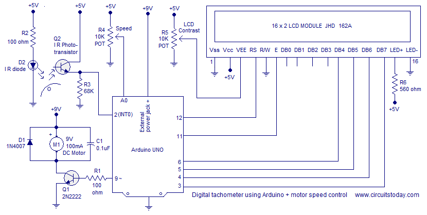
Tachometer is a device used for measuring the number of revolutions of an object in a given interval of time. Usually it is expressed in revolutions per minute or RPM. Earlier tachometers purely mechanical where the revolution is transferred to the tachometer through mechanical coupling (cable or shaft) , the rpm is determined using a gear mechanism and it is displayed on a dial. With the advent of modern electronics, the tachometers have changed a lot. This article is about a contactless digital tachometer using Arduino. The speed of the motor can be also controlled using the same circuit. The RPM and all the other information’s are displayed on a 16×2 LCD screen. The circuit diagram of the digital tachometer using Arduino is shown below.
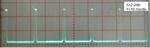
Counting the RPM.
Arduino is used for counting the RPM and displaying it on the LCD screen. Emitter of the photo transistor is connected to the Interrupt 0 (digital pin 2) of the Arduino. The Arduino interrupt is configured to be rising edge triggered. As a result the will be an interrupt for every upward shoot in the emitter waveform. The number of interrupts occurred in a given time is counted by incrementing a variable using the interrupt service routine.
The time elapsed during the counting cycle is determined using the millis() function. The millis() function returns the number of milli seconds passed since the Arduino board is switched ON. Calling the millis() function before and after the counting cycle and the taking their difference gives the times passed during the counting cycle. The (number of interrupts/time in milliseconds)*60000 will give the revolutions per minute (RPM).
Read More: Tachometer using Arduino
- What is the primary function of this device?
The device measures the number of revolutions of an object in a given interval of time. - How does the system count the RPM?
Arduino counts interrupts triggered by upward shoots in the emitter waveform from the photo transistor. - Which Arduino pin connects to the photo transistor?
The emitter of the photo transistor connects to Interrupt 0, which is digital pin 2. - Does the circuit support motor speed control?
Yes, the speed of the motor can be controlled using the same circuit. - How is the time elapsed during the counting cycle determined?
The millis() function is called before and after the cycle to find the difference in milliseconds. - What formula calculates the revolutions per minute?
The calculation is the number of interrupts divided by time in milliseconds multiplied by 60000. - Where is the RPM information displayed?
All information including RPM is shown on a 16×2 LCD screen. - How is the Arduino interrupt configured?
The interrupt is set to rising edge triggered mode.
