This is a little art project I made with 95 RGB LEDs arranged in a 3D cylinder shape, sitting atop a microcontroller-based driver circuit. The LEDs are individually addressable, and when you power it on, the software cycles through a series of animations, e.g. various moving rainbowy patterns, “rain”, “fireworks”, and so on. It doesn’t serve much of a purpose but it is kind of cool to look at. The hardware and software are open source, so feel free to use/copy/extend whatever you find here (subject to the CC/GPL license terms). If you have questions, you can e-mail me, or better yet, post a comment to the NYC Resistor blog and I will post a response there. Thanks!
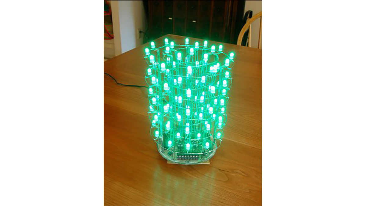
The LEDs are 4-lead T1 3/4 RGB common anode with a diffused case. I got them on eBay from HKJE Lamp Center for about 30 cents each, including shipping from Hong Kong. Despite the low cost, they seem to be of very good quality. They are wired together using music wire (bare steel wire) from Pearl Paint. Adam Mayer used this wire in his MegaScroller project and he showed me how to work with it. It’s a pain in the neck to solder (sand it first and then apply paste flux) but it is very strong. Props to the other resistors who helped assemble the cage. It was a lot of soldering.
The LEDs are wired in a 5-way multiplexed grid. The anodes of all 19 LEDs in each plane are connected together. The cathodes of each LED are connected to the cathodes of the four other LEDs in the same vertical column. So the matrix of LEDs has five anodes and 57 cathodes (19 LEDs per plane * 3 cathodes per LED). The driver circuit uses five IRLU3715PBF N channel mosfets to switch +5 volts to the anode lines, and four TLC5940NT 16 channel PWM constant-current LED driver chips to switch the cathodes to ground. Since I’m using N channel mosfets as high side switches, I need to generate a gate voltage that is higher than Vdd. I use a simple charge pump to double the +5V coming from my power supply, and switch it to the mosfet gates using three TC4427ACPA mosfet drivers. The mosfets are IRL series (i.e. logic level) so they are fully switched on with Vgs of +5v. Rds-on is in the range of 15-20 milliohms. The TLC5940s are set to sink about 20ma per channel. The LEDs are rated for 20ma steady state, and I’m only driving them at a 20% duty cycle, so In theory I could probably increase the current to around 100ma, but it is surprisingly bright as-is so I haven’t felt a need to experiment with higher currents.
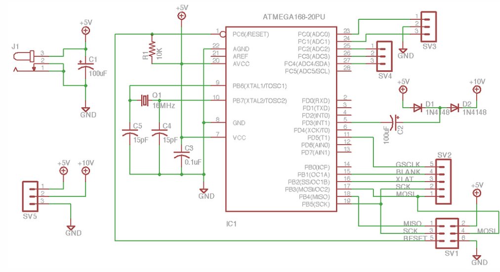
The driver circuit consists of two stacked boards connected via pin headers. The top board is a round two layer board about four inches in diameter. I designed it in Eagle and etched at home using the toner transfer method. The bottom board is a standard RadioShack perfboard. It only has the microcontroller and a few other components. It is wired using point-to-point wiring. I did it this way so that in the future I can add extra capability to the circuit (e.g. audio input, USB, or a ZigBee interface) without re-doing the whole project.
[box color=”#985D00″ bg=”#FFF8CB” font=”verdana” fontsize=”14 ” radius=”20 ” border=”#985D12″ float=”right” head=”Major Components in Project” headbg=”#FFEB70″ headcolor=”#985D00″]Arduino[/box]
For more detail: LED Cylinder using Arduino