Summary of IoT Based Patient Monitoring System using ESP8266 and Arduino
This project builds an IoT patient monitoring system using an Arduino Uno and ESP8266 to record heart rate and body temperature, log data to ThingSpeak and Google Sheets, and send email/SMS alerts via IFTTT when readings cross thresholds or a panic button is pressed. Sensors (pulse sensor and LM35) feed Arduino, which communicates with ESP8266 via AT commands to POST data. ThingSpeak ThingHTTP and React apps trigger IFTTT applets for logging and alerts. Code handles WiFi connection, periodic readings, ThingSpeak updates, and panic button reporting.
Parts used in the IoT based Patient Monitoring System using ESP8266 and Arduino:
- Arduino Uno
- ESP8266 Wi-Fi module (ESP8266-01)
- LM35 temperature sensor
- Pulse rate sensor (Pulse Sensor)
- Push button (panic button)
- 10k Resistor
- Male-female wires
- Breadboard
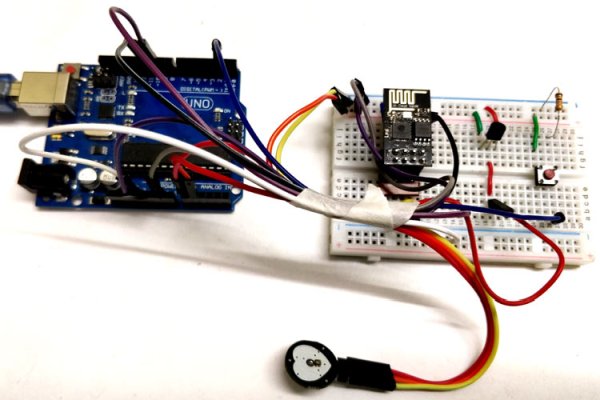
IoT based Patient Monitoring System using ESP8266 and Arduino
Health monitoring is the major problem in today’s world. Due to lack of proper health monitoring, patient suffer from serious health issues. There are lots of IoT devices now days to monitor the health of patient over internet. Health experts are also taking advantage of these smart devices to keep an eye on their patients. With tons of new healthcare technology start-ups, IoT is rapidly revolutionizing the healthcare industry.
Here in this project, we will make an IoT based Health Monitoring System which records the patient heart beat rate and body temperature and also send an email/SMS alert whenever those readings goes beyond critical values. Pulse rate and body temperature readings are recorded over ThingSpeak and Google sheets so that patient health can be monitored from anywhere in the world over internet. A panic will also be attached so that patient can press it on emergency to send email/sms to their relatives.
Materials required
- Arduino Uno
- ESP8266 Wi-Fi module
- LM35 temperature sensor
- Pulse rate sensor
- Push button
- 10k Resistor
- Male-female wires
- Breadboard
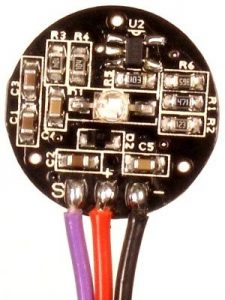
Pulse Rate Sensor
Pulse Sensor is a well-designed plug-and-play heart-rate sensor for Arduino. The sensor clips onto a fingertip or earlobe and plugs right into Arduino. It also includes an open-source monitoring app that graphs your pulse in real time.
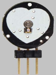
The front of the sensor is the covered with the Heart shape logo. This is the side that makes contact with the skin. On the front you see a small round hole, which is where the LED shines through from the back, and there is also a little square just under the LED. The square is an ambient light sensor, exactly like the one used in cellphones, tablets, and laptops, to adjust the screen brightness in different light conditions. The LED shines light into the fingertip or earlobe, or other capillary tissue, and sensor reads the amount of light that bounces back. That’s how it calculates the heart rate. The other side of the sensor is where the rest of the parts are mounted.
Before we use this sensor, we need to protect the exposed side of the sensor so that we can get accurate readings and avoid the short circuit due to sweat. For this, you can use Velcro strip or black tape. As shown in the picture.
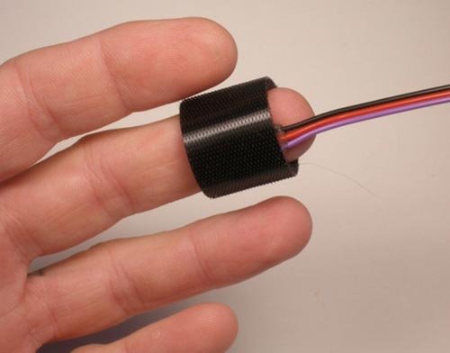
There are three wires coming out of the sensor, Signal(S), Vcc(3 – 5 V) and GND.
Signal wire is connected to Arduino Analog pin. The same sensor is used in our Arduino Heart Beat monitoring project.
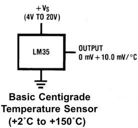
LM35 Temperature Sensor
LM35 is a analog linear temperature sensor. Its output is proportional to the temperature (in degree Celsius). The operating temperature range is from -55°C to 150°C. The output voltage varies by 10mV in response to every oC rise or fall in temperature. It can be operated from a 5V as well as 3.3 V supply and the stand by current is less than 60uA.

ESP8266-01
Most people call ESP8266 as a WIFI module, but it is actually a microcontroller. ESP8266 is the name of the microcontroller developed by Espressif Systems which is a company based out of shanghai. This microcontroller has the ability to perform WIFI related activities hence it is widely used as a WIFI module.

There are two of ways to work with your ESP8266 module. This tutorial will help you to get started with ESP8266. One way is by using the AT commands. The other way is by using the Arduino IDE. Here we will use AT commands to send data from Arduino to ESP.
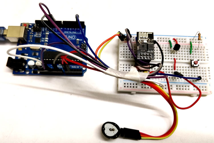
Circuit Diagram
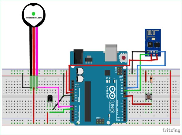
Below are the connections:
- Signal pin of pulse sensor -> A0 of arduino
- Vcc pin of pulse sensor -> 5V of arduino
- GND pin of pulse sensor -> GND of arduino
- Vout of LM35 -> A1 of Arduino
- Tx of ESP8266 -> pin 10 of arduino
- Rx of ESP8266 -> pin 11 of arduino
- CH_PD and Vcc of ESP8266 -> 3.3 V of arduino
- GND of ESP8266 -> GND of arduino
- Push button -> digital pin 8 of arduino
Configuring ThingSpeak to record Patient Data online
ThingSpeak provides very good tool for IoT based projects. By using ThingSpeak site, we can monitor our data and control our system over the Internet, using the Channels and webpages provided by ThingSpeak. ThingSpeak ‘Collects’ the data from the sensors, ‘Analyze and Visualize’ the data and ‘Acts’ by triggering a reaction. We have previously used ThingSpeak in Weather station project using Raspberry Pi and using Arduino, check them to learn more about ThingSpeak. Here we are briefly explaining to use ThingSpeak for this IoT Patient Monitoring Project.
We will use ThingSpeak to monitor patient heartbeat and temperature online using internet. We will also use IFTTTplatform to connect ThingSpeak to email/message service so that alert message can be sent whenever the patient is in critical state.
Step 1:- First of all, user needs to Create a Account on ThingSpeak.com, then Sign In and click on Get Started.

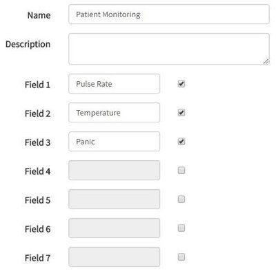
Step 2:- Now go to the ‘Channels’ menu and click on New Channel option on the same page for further process.

Step 3:- Now you will see a form for creating the channel, fill in the Name and Description as per your choice. Then fill ‘Pulse Rate’, ‘Temperature’ and ‘Panic’ in Field 1, Field 2 and Field 3 labels, tick the checkboxes for the Fields. Also tick the check box for ‘Make Public’ option below in the form and finally Save the Channel. Now your new channel has been created.
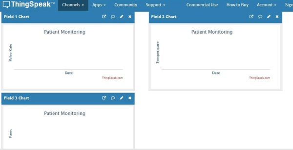
Step 4:- You will see three charts as shown below. Note the Write API key, we will use this key in our code.
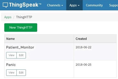
Step 5:- Now, we will use ThingHTTP app of the server to trigger the IFTTT applet for data entry to Google sheets and send email/sms. ThingHTTP enables communication among devices, websites, and web services without having to implement the protocol on the device level. You can specify actions in ThingHTTP, which you want to trigger using other ThingSpeak apps such as React.
To make New ThingHTTP, we will need URL for triggering which we will get from IFTTT.
Configuring IFTTT for triggering Mail/SMS based on ThingSpeak Values
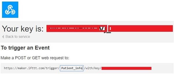
Step 1:- Login to IFTTT and search for Webhooks and click on it.

Step 2:- Click on Documentation.

Step 3:- Type “Patient_Info” in the event box and copy the URL. We will use this URL in ThingHTTP.
Now let’s make Applet to link ThingHTTP to Google sheet and to send email/sms. After that we will jump to complete our ThingHTTP.
Step 4:- Click on New Applete in My Applete option.

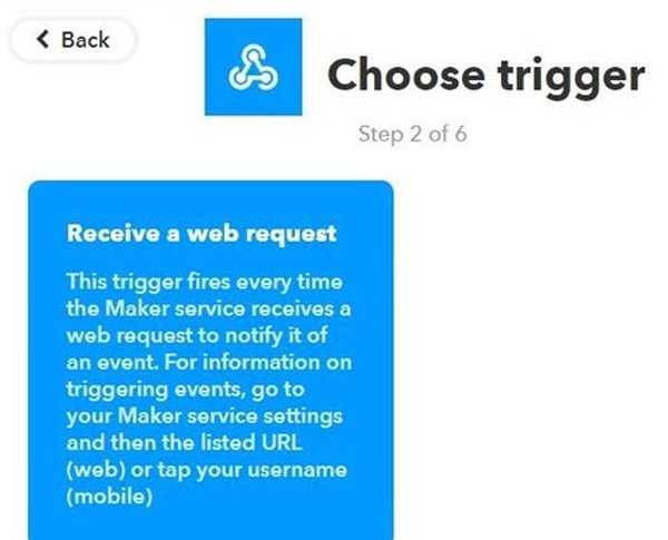
Step 5:- Click on “+this” and search for Webhooks and click on it. Choose trigger as “Receive a web request”.
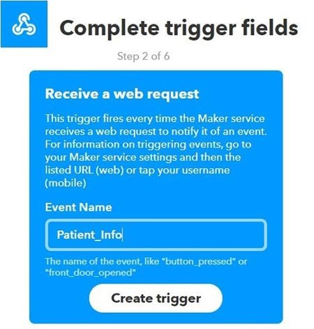
Step 6:- Type the Event Name which is same as you write in the event box in webhooks URL. Click on Create Trigger.
Step 7:- Click on “+that” and search for Google Sheets and click on it.
Click on Add row to spreadsheet.

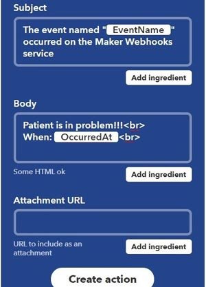
Step 8:- Give any name to your sheet. In formatted row box, you have date and time, event name, BPM value and body temperature which will be written as shown.

Step 9:- Review your applet and click on finish.

In the same way, we have to make applet for sending email when Panic event is occurred.
So again click on “+this” and select Webhooks, then in event name enter “Panic”. In “+that” search for Gmail and click on it.
Now, click on Send an email.

Type the email addresses on which you wish to receive email when there is a panic to the patient.

Type the body content you wish to send in the email and click on create action. Review it and finish.
We have made our applets to perform the tasks. Now, come back to Thingspeak->Apps->ThingHTTP.
ThingHTTP for connecting ThingSpeak with IFTTT
Step 1:- Click on New ThingHTTP. Give any name and Paste the URL that you copied from the webhooks documentation. Fill Remaining information as shown below.

In Body, we have to write the information that we want to send to the IFTTT applet. We are sending patient Pulse reading and temperature. So the format is
{ “value1” : “%%channel_channelID_field_fieldNumber%%”,”value2″ : “%%channel_channelID_field_fieldNumber%%”}

After filling these informations, click on Save ThingHTTP.
In the same manner, we have to make ThingHTTP for “Panic”. Follow the same steps.
In URL, write Panic in place of Patient_Info. Body remains empty and All other information are same as in previous ThingHTTP. Save it.
Now, we have to make React to trigger the URL.
React works with ThingHTTP app to perform actions when channel data meets a certain condition.
To make React, click on Apps -> React. Click on New React.
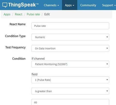
Step 2:- Give name to your React. Condition type as Numeric and Test Freaquency as on Data Insertion.
Choose the Condition on which you want to trigger the URL. Select your channel from the If Channel drop down menu. Choose field 1 i.e Pulse rate and make condition of greater than any value. I have used 60. As shown
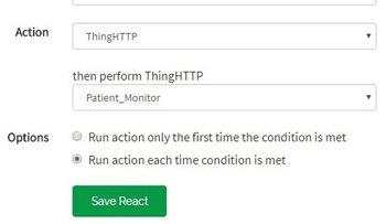
Choose ThingHTTP from Action drop down menu and select the ThingHTTP.
Select “Run action each time condition is met” and click on Save React.
In the same way, make React for the Panic as shown.
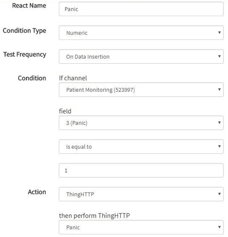
Select “Run action each time condition is met” and click on Save React.
We have done with Web based work. Now, we will see code for Arduino.
Arduino Code Explanation
Complete Arduino code is given at the end, here we are explaining few important part of it. We will use library for Pulse rate sensor which can be downloaded from this Link. Also, we are using timer to set interval to take readings. For this we need Timer library, which can be downloaded from this Link.
Let’s jump to coding part…
First, we include all the libraries. We are using software serial to communicate with esp8266.
#include <SoftwareSerial.h>
#include “Timer.h”
#include <PulseSensorPlayground.h> //pulse sensor library
Make instance for timer, SoftwareSerial and pulse sensor to use in our code.
Timer t;
PulseSensorPlayground pulseSensor;
SoftwareSerial esp8266(10,11); //Rx,Tx
Set-up low-level interrupts for most accurate BPM match and enable DEBUG to show ongoing commands on serial monitor.
#define USE_ARDUINO_INTERRUPTS true
#define DEBUG true
Set your WiFi name , password and IP of thingspeak.com
#define SSID “*********” // “your WiFiname”
#define PASS “**********” // “wifi password”
#define IP “184.106.153.149” // thingspeak.com ip
Declare String to update information on ThingSpeak channel. You will need API key for this, which can be found from your ThingSpeak channel-> API key . Copy Write API key and paste here.
String msg = “GET /update?key=Your Api Key”;
In setup function, set the baud rate for serial communication between Arduino serial monitor and esp8266. Start the ESP communication by giving AT command to it and connect it by calling connectWiFi(); function. After that we will initialize Timers by calling t.every(time_interval, do_this); which will take the readings of the sensors and update on the channel after every time_interval you defined.
void setup()
{
Serial.begin(9600);
esp8266.begin(115200);
pulseSensor.analogInput(PulseWire);
pulseSensor.blinkOnPulse(LED13); //auto-magically blink Arduino’s LED with heartbeat.
pulseSensor.setThreshold(Threshold);
// Double-check the “pulseSensor” object was created and “began” seeing a signal.
if (pulseSensor.begin()) {
Serial.println(“We created a pulseSensor Object !”);
}
Serial.println(“AT”);
esp8266.println(“AT”);
delay(3000);
if(esp8266.find(“OK”))
{
connectWiFi();
}
t.every(10000, getReadings);
t.every(10000, updateInfo);
}
We have to make functions for connectWiFi(), panic_button(), update_info() and getReadings().
Make function for connectWiFi() which will return True or False depending upon Wi-Fi connected or not. AT+CWMODE=1 will make ESP8266 work in station mode. AT+CWJAP=\, command, used in this function, is to connect to your Access Point (your Wi-Fi router).
boolean connectWiFi()
{
Serial.println(“AT+CWMODE=1”);
esp8266.println(“AT+CWMODE=1”);
delay(2000);
String cmd=”AT+CWJAP=\””;
cmd+=SSID;
cmd+=”\”,\””;
cmd+=PASS;
cmd+=”\””;
Serial.println(cmd);
esp8266.println(cmd);
……
…..
Make getReadings(); function to take pulse sensor and LM35 readings and convert them to string using dtostrf();function.
void getReadings(){
raw_myTemp = analogRead(A1);
Voltage = (raw_myTemp / 1023.0) * 5000; // 5000 to get millivots.
tempC = Voltage * 0.1; //in degree C
myTemp = (tempC * 1.8) + 32; // conver to F
Serial.println(myTemp);
int myBPM = pulseSensor.getBeatsPerMinute(); // Calls function on our pulseSensor object that returns BPM as an “int”.
if (pulseSensor.sawStartOfBeat()) { // Constantly test to see if “a beat happened”.
Serial.println(myBPM); // Print the value inside of myBPM.
}
delay(20);
Define char array for BPM and temp and convert float value of these sensors to String using dtostrf().
char buffer1[10];
char buffer2[10];
BPM = dtostrf(myBPM, 4, 1, buffer1);
temp = dtostrf(myTemp, 4, 1, buffer2);
}
Make function for updating sensor information on the ThingSpeak channel.
“AT+CIPSTART=\”TCP\”,\””, AT Command will establish TCP command over port 80
void updateInfo()
{
String cmd = “AT+CIPSTART=\”TCP\”,\””;
cmd += IP;
cmd += “\”,80″;
Serial.println(cmd);
esp8266.println(cmd);
delay(2000);
if(esp8266.find(“Error”))
{
return;
}
Attach the readings with the GET URL using “&field1=”; for pulse readings and “&field2=”; for temperature readings. Send this information using “AT+CIPSEND=” command.
  cmd = msg ;
  cmd += "&field1=";    //field 1 for BPM
  cmd += BPM;
  cmd += "&field2=";  //field 2 for temperature
  cmd += temp;
  cmd += "\r\n";
  Serial.print("AT+CIPSEND=");
  esp8266.print("AT+CIPSEND=");
  Serial.println(cmd.length());
  esp8266.println(cmd.length());
  if(esp8266.find(">"))
  {
    Serial.print(cmd);
    esp8266.print(cmd);
  }
…
…
Similarly, make function for panic_button. When button goes to HIGH, esp8266 send the information to the server using AT+CIPSTART and AT+CIPSEND commands.
void panic_button(){
  panic = digitalRead(8);
    if(panic == HIGH){
    Serial.println(panic);
      String cmd = "AT+CIPSTART=\"TCP\",\"";
  cmd += IP;
  cmd += "\",80";
  Serial.println(cmd);
  esp8266.println(cmd);
…..
..
Attach this information to “&field3=“.
  cmd = msg ;
  cmd += "&field3=";
In loop function, call panic_button() and timers using t.update() function .
void loop()
{
  panic_button();
start: //label
    error=0;
    t.update();
……
……
Patient Monitoring System in Action
Now, connect your hardware components according to the circuit diagram and upload the code to the Arduino. Open Serial monitor to see what’s going inside the code.
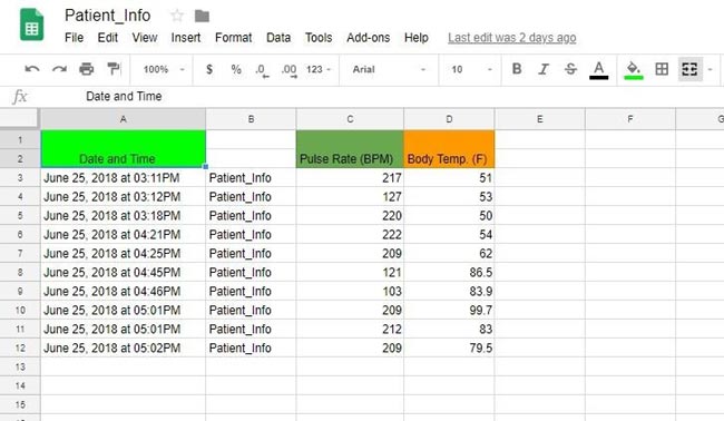
You will see data is updated defined in the Google sheets on Google drive, after the interval you defined in the timer setting.
Press panic button for 4-5 seconds, you will get email that patient is in problem, like shown below:

Check the demonstration Video given below.
#define USE_ARDUINO_INTERRUPTS true
#define DEBUG true
#define SSID “********” // “SSID-WiFiname”
#define PASS “************” // “password”
#define IP “184.106.153.149” // thingspeak.com ip
#include <SoftwareSerial.h>
#include “Timer.h”
#include <PulseSensorPlayground.h> // Includes the PulseSensorPlayground Library.
Timer t;
PulseSensorPlayground pulseSensor;
String msg = “GET /update?key=your api key”;
SoftwareSerial esp8266(10,11);
//Variables
const int PulseWire = A0; // PulseSensor PURPLE WIRE connected to ANALOG PIN 0
const int LED13 = 13; // The on-board Arduino LED, close to PIN 13.
int Threshold = 550; //for heart rate sensor
float myTemp;
int myBPM;
String BPM;
String temp;
int error;
int panic;
int raw_myTemp;
float Voltage;
float tempC;
void setup()
{
Serial.begin(9600);
esp8266.begin(115200);
pulseSensor.analogInput(PulseWire);
pulseSensor.blinkOnPulse(LED13); //auto-magically blink Arduino’s LED with heartbeat.
pulseSensor.setThreshold(Threshold);
// Double-check the “pulseSensor” object was created and “began” seeing a signal.
if (pulseSensor.begin()) {
Serial.println(“We created a pulseSensor Object !”); //This prints one time at Arduino power-up, or on Arduino reset.
}
Serial.println(“AT”);
esp8266.println(“AT”);
delay(3000);
if(esp8266.find(“OK”))
{
connectWiFi();
}
t.every(10000, getReadings);
t.every(10000, updateInfo);
}
void loop()
{
panic_button();
start: //label
error=0;
t.update();
//Resend if transmission is not completed
if (error==1)
{
goto start; //go to label “start”
}
delay(4000);
}
void updateInfo()
{
String cmd = “AT+CIPSTART=\”TCP\”,\””;
cmd += IP;
cmd += “\”,80″;
Serial.println(cmd);
esp8266.println(cmd);
delay(2000);
if(esp8266.find(“Error”))
{
return;
}
cmd = msg ;
cmd += “&field1=”; //field 1 for BPM
cmd += BPM;
cmd += “&field2=”; //field 2 for temperature
cmd += temp;
cmd += “\r\n”;
Serial.print(“AT+CIPSEND=”);
esp8266.print(“AT+CIPSEND=”);
Serial.println(cmd.length());
esp8266.println(cmd.length());
if(esp8266.find(“>”))
{
Serial.print(cmd);
esp8266.print(cmd);
}
else
{
Serial.println(“AT+CIPCLOSE”);
esp8266.println(“AT+CIPCLOSE”);
//Resend…
error=1;
}
}
boolean connectWiFi()
{
Serial.println(“AT+CWMODE=1”);
esp8266.println(“AT+CWMODE=1″);
delay(2000);
String cmd=”AT+CWJAP=\””;
cmd+=SSID;
cmd+=”\”,\””;
cmd+=PASS;
cmd+=”\””;
Serial.println(cmd);
esp8266.println(cmd);
delay(5000);
if(esp8266.find(“OK”))
{
return true;
}
else
{
return false;
}
}
void getReadings(){
raw_myTemp = analogRead(A1);
Voltage = (raw_myTemp / 1023.0) * 5000; // 5000 to get millivots.
tempC = Voltage * 0.1;
myTemp = (tempC * 1.8) + 32; // conver to F
Serial.println(myTemp);
int myBPM = pulseSensor.getBeatsPerMinute(); // Calls function on our pulseSensor object that returns BPM as an “int”.
// “myBPM” hold this BPM value now.
if (pulseSensor.sawStartOfBeat()) { // Constantly test to see if “a beat happened”.
Serial.println(myBPM); // Print the value inside of myBPM.
}
delay(20);
char buffer1[10];
char buffer2[10];
BPM = dtostrf(myBPM, 4, 1, buffer1);
temp = dtostrf(myTemp, 4, 1, buffer2);
}
void panic_button(){
panic = digitalRead(8);
if(panic == HIGH){
Serial.println(panic);
String cmd = “AT+CIPSTART=\”TCP\”,\””;
cmd += IP;
cmd += “\”,80″;
Serial.println(cmd);
esp8266.println(cmd);
delay(2000);
if(esp8266.find(“Error”))
{
return;
}
cmd = msg ;
cmd += “&field3=”;
cmd += panic;
cmd += “\r\n”;
Serial.print(“AT+CIPSEND=”);
esp8266.print(“AT+CIPSEND=”);
Serial.println(cmd.length());
esp8266.println(cmd.length());
if(esp8266.find(“>”))
{
Serial.print(cmd);
esp8266.print(cmd);
}
else
{
Serial.println(“AT+CIPCLOSE”);
esp8266.println(“AT+CIPCLOSE”);
//Resend…
error=1;
}
}
}
Video:
Attach the readings with the GET URL using “&field1=”; for pulse readings and “&field2=”; for temperature readings. Send this information using “AT+CIPSEND=” command.
Source : IoT Based Patient Monitoring System using ESP8266 and Arduino
- What does the system monitor?
It monitors patient pulse rate and body temperature and logs them online. - How are alerts sent when readings are critical?
ThingSpeak React triggers ThingHTTP which calls IFTTT applets to send email or SMS alerts. - Can the patient send an immediate alert manually?
Yes, pressing the panic push button sends a panic field update that triggers an email via IFTTT. - How does Arduino communicate with the internet?
Arduino sends data to the ESP8266 using SoftwareSerial and ESP8266 uses AT commands to connect to WiFi and ThingSpeak. - Where are the sensor readings recorded online?
Readings are recorded on ThingSpeak and forwarded to Google Sheets via IFTTT. - What sensors are used for heart rate and temperature?
Pulse Sensor for heart rate and LM35 for temperature. - How often are readings taken and sent?
Timers are set in the code to take readings and update the channel at the defined interval (example uses 10000 ms in code). - What AT command sets ESP8266 to station mode?
AT+CWMODE=1 sets the ESP8266 to station mode as used in the connectWiFi function.