PROBLEM: Making my Arduino, a Temperature-Relative Humidity sensor and a Nokia3310LCD screen work together.
Now, I’m a Lazy Old Geek, so what I wanted was an Arduino kit that would take shields. This Freeduino was the cheapest that I could find at the time.
http://www.seeedstudio.com/depot/freeduino-usb-complete-kit-p-58.html?cPath=79_82
Since I was at Seeedstudio, I also ordered an HSM-20G Temp-RH sensor as it was on closeout and I needed something to try out my Arduino with. Seeedstudio no longer carries these and they’re hard to find. But here’s one site that sells the HSM-20G.
http://www.emartee.com/product/41488/#
My dog, Marcus and I walk every day, so I decided I needed a portable Arduino to display Temp-RH on our walks. My display choice was the Nokia3310LCD shield. Plus it has a cool, little joystick on it.
http://www.nuelectronics.com/estore/index.php?main_page=product_info&cPath=1&products_id=12
So here’s the problems and processes I went through to make it all work.
Parts:
USB Freeduino kit $22
HSM-20G Temp-RH $9 (Closeout)
Nokia3310LCD $14.99
Prices US dollars August 2010
 nokia_3310_lcd.zip32 KB
Step 1: Connecting the HSM-20G
Here’s the suggested interface circuitry for the HSM-20G. See picture.
Problem 1: The Nokia3310 shield fits on the Freeduino but I didn’t want to connect the HSM-20G to the shield. There’s only three components in the interface but I didn’t have a protoshield or any prototype area on the Nokia3310LCD shield, so I decided to build the interface onto the HSM-20G PCB. This is reasonable as it will always be needed whenever I used the HSM-20G. So I soldered the 10K to the T output and to a ground on the top side of the PCB. See picture.
Caution: This method is not recommended for the inexperienced.
A ground pin can be found by following the Ground (-) on the connector and tracing it on the PCB. The best way to verify that it is ground is to set your DMM to ohms and measure between the (-) pin of the connector and the pin you suspect is ground. It should be shorted (less than an ohm).
Problem 2: Well, I didn’t have a 47uFd capacitor, but I scrounged a 22uFd capacitor from some scrapped printer PCBs. I can tell from the documentation, that all the capacitor does is smooth out the Relative Humidity voltage, so 22uFd should work just fine. So I solder the capacitor to the 100K resistor, then soldered the resistor lead to the H pin on the connector making sure the positive side of the electrolytic capacitor is on this side. Then solder the other side of the resistor to the 10K resistor lead that is soldered to ground. See picture.
Make sure all of the leads aren’t touching other components and there are no solder bridges.
Problem 3: There was no mating connector for the HSM-20G module or a part number. I emailed Seeeduino requesting the brand and part number and of course got no response. But I scrounged through my junk pile and found a connector that worked.
Problem 4: How do I connect it to the Arduino? The preferred way would be to get one of those stackable protoshields and connect the HSM-20G to it. You could also put the interface circuitry on the protoshield. But I didn’t have one.
NOT RECOMMENDED: So I soldered the connector directly to my Freeduino. The (+) goes to a 5V connection. The (-) goes to a ground. The ‘H’ connects to Analog 1 and the ‘T’ to Analog 2.
Caution: When connecting two different sensors or shields, you have to be careful about not overlapping Analog and Digital pins. I started an Excel spreadsheet that has all of my shields and the pins they use. The Nokia3310 shield uses Analog 0 for the joystick so Analog 1 and 2 are available for the HSM-20G.
Here is the site where I found the sample HSM-20G sketch. This person really seems to know what he’s talking about. I verified the formulas with the HSM-20G data sheet. They are very accurate. There are other sensor interfaces on this page, also.
http://sites.google.com/site/measuringstuff/more-sensor-examples#TOC-HSM-20G-Humidity-and-Temperature-Mi
So I was able to run this sample HSM-20G sketch and display temperature and humidity on the PC monitor.
Step 2: Connecting the Nokia3310LCD with joystick shield
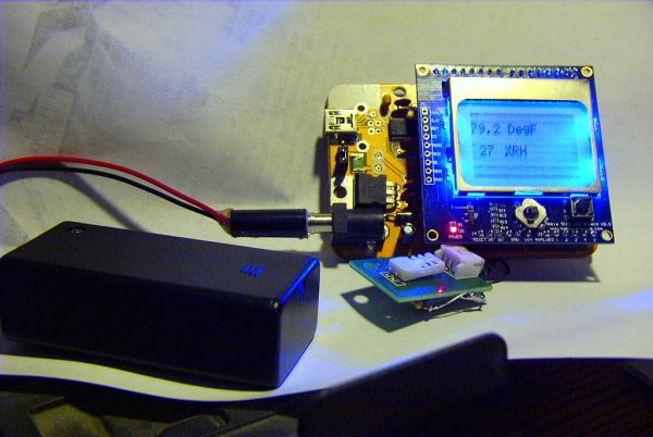
So, this is easy, just take the shield (see picture). Plug it in. Load the sample sketch and run it. Right?
Problem 5: Well, not so fast. When I first tried it, the LCD screen was dark and hard to read. When I powered it up with an external 9V battery, it was unreadable.
So I emailed nuelectronics with my problem and of course, got no response.
Solution 1?: I wondered why the LCD was better with USB power than with external power. So I measured the 5V. See picture. It was 4.84V. The power was coming from my PC but it was also going through an unpowered USB hub and 4.84V is acceptable. I measured the same place using a 9V battery connected to the 7805 regulator. The voltage was 5.03V, about what I expected.
The tiny LED in my head blinked. I decided the LCD would be more readable if I dropped the ‘5V’ voltage to the Freeduino and the Nokia LCD.
My Freeduino has the typical power supply like the schematic. All I had to do was remove the PWR SEL jumper and replace it with a potentiometer (variable resistor) on pins 1 and 2. (or 2 and 3 if using USB power)
So I scrounged a three pin connector with wires on it and solder two wires to a scrounged 200 ohm potentiometer. For those of you not familiar with potentiometers, they are a resistor with a mechanical wiper that can move from 0 ohms to the maximum (200 in this case). Why 200, well it was the smallest resistance I could find. Potentiometers have three leads. You only need two connections, make sure you solder one to the variable pin. See picture. Then plug it in, see next picture.
So this worked pretty good. I could tweak the potentiometer to get a nice display on the screen. BUT. . .
Step 3: Temperature and humidity?
So now what’s wrong? I did some thinking (dangerous thing to do for an OLD man). I wonder what changing the 5V does to reading analog voltages. Sure enough, I ran the HSM-20G demo, the temperature and humidity varied with the DC voltage for the Arduino. For a full explanation, I put the Analog to Digital Conversion in another step so most of you can skip it.
Solution 2?: Well, I thought one option was to run the Arduino at 5V and adjust the voltage on the Nokia3310 shield. There didn’t seem any easy way to do that.

Solution 3?: There are ways to set up the Arduino Analog converters so it doesn’t need 5V but this would require a lot of software changes and experimenting, plus I had to consider the joystick was analog also and was already designed for 5V.
Solution 4: While searching around for solutions, I found this website:
http://blog.thiseldo.co.uk/?p=383
‘Andy’ rewrote the libraries for the Nokia3310. I downloaded them and took a look. One of the comments said the initialization of the LCD was updated for a newer version of the LCD that nuelectronics was using. AHA! So I haven’t figured out how Andy found this out from the nuelectronics website, I couldn’t but it would’ve been nice if they’d updated their libraries.
[box color=”#985D00″ bg=”#FFF8CB” font=”verdana” fontsize=”14 ” radius=”20 ” border=”#985D12″ float=”right” head=”Major Components in Project” headbg=”#FFEB70″ headcolor=”#985D00″]USB Freeduino kit
HSM-20G Temp-RH
Nokia3310LCD[/box]
For more detail: Nokia LCD & Sensors using an Arduino