Summary of True Analog Audio Volume Control using Arduino
This article details a "True Analog Audio Volume Control" (T.A.A.V.C.) project using an Arduino to regulate audio levels via tungsten filament bulbs. The author rejects digital pots, mechanical servos, vacuum tubes, and toxic opto-isolators in favor of pure metal resistance. The design utilizes five 2.5V mini light bulbs arranged in two attenuation stages, with resistance controlled by DC current from an LM4863 differential power amplifier IC. This setup allows for precise volume adjustment while maintaining high fidelity and avoiding semiconductors or toxic materials in the audio path.
Parts used in the True Analog Audio Volume Control:
- Arduino
- Tungsten wire light bulbs (5 units, 2.5V, ~200mA)
- Resistive component (1 unit)
- Differential Power Amplifier IC LM4863
- 5V regulated switching power supply (4A)
ow my Arduino can precisely measure audio input (VU meter), and obviously, next thing that comes to mind right after measurements, is regulation or control. There are many different ways how to electronically adjust audio volume or level of AC signal. I’ll name a few:
- Specifically design IC, Digital potentiometers.
- Mechanical potentiometers, driven by servo / motors.
- Vacuum tubes amplifiers in “variable-mu” configuration.
- Resistive opto-isolators.
First category (#1) fits nicely for arduino project. But it’s not interesting to me. My apologies to someone, who was searching an example of interface between arduino and digital pot. Other people don’t tolerate semiconductors in audio path ( tube sound lovers ). Third option would make them happy, only (#3) requires high voltage and difficult to accomplish on low hobbyist budget, so I left it out of the scope. Mechanical pot (#2) would be good solution to satisfy Hi-Fi perfectionists and arduino fans. The same time response time of mechanical parts is too slow, verdict – discarded. (#4) have been in use since 1960s, but would you like your lovely music to be adjusted by highly toxic CdSe / CdS ? I don’t think so. Wiki says opto-isolators have low THD distortion level, less than 0.1%. Probably true, but apart from technical aspect, there is always psychological, poisonous CdSe affects my perception.
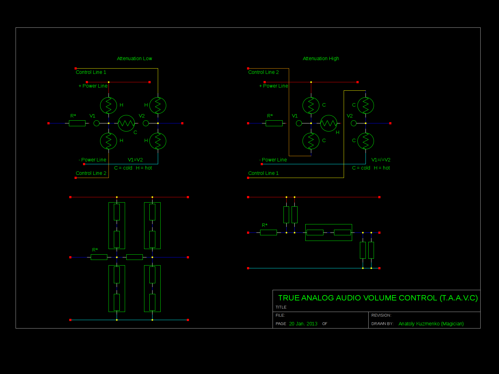
How about variable resistor in it’s simplest form – tungsten wire? Where you can get one? In the electrical bulb. Perfect material for audiophiles – where distortion could get into ? – It’s pure metal ! And here is my design of the “basic cell” – True Analog Audio Volume Control (T.A.A.V.C.)
As you can see, cell consists of 5 bulbs plus 1 resistor. All elements form 2 attenuation stages, basically – voltage dividers with variable resistors. Resistive values of bulbs proportional to temperature, which is easy to control passing DC current through. To make it work with the biggest possible dynamic range, middle bulb is also heated up by current flow from two differential control lines / phases.
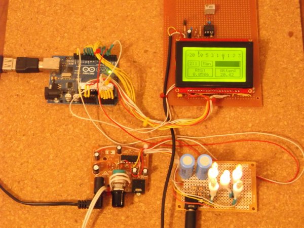
Hardware prototype / Proof of Concept.
Differential Power Amplifier (PA) IC LM4863 is used as DC current source for control lines. Circuitry powered from 5V regulated switching power supply (4A). Bulbs – clear mini lights, 2.5V, approximately 200 mA. Cold state resistance about 1.2 – 1.5 Ohm, hot state resistance is rising up to 15 Ohm. Volume regulator could be connected to any audio source with output impedance no more than 32 Ohm, for example, headphones output. For test I used second channel of the PA, that shown in “optional” box on the left side. Second channel is a “nice to have” feature in stereo version of the project, when both channels would drive two separate TAAVC cells, so using it as a “buffer” amplifier may be not an option.
For more detail: True Analog Audio Volume Control using Arduino
- Why did the author reject digital potentiometers?
The author found them uninteresting for this specific project. - What is the primary material used for the variable resistor?
Tungsten wire taken from electrical light bulbs. - How does the resistance of the bulbs change during operation?
Cold state resistance is about 1.2 to 1.5 Ohm, rising to 15 Ohm when hot due to temperature control via DC current. - Which IC is used as the DC current source for the control lines?
A Differential Power Amplifier IC LM4863. - What is the maximum output impedance for the connected audio source?
The volume regulator requires an audio source with an output impedance no more than 32 Ohm. - How are the bulbs arranged in the circuit design?
All elements form 2 attenuation stages acting as voltage dividers with variable resistors. - Why were mechanical potentiometers discarded for this project?
Their response time is considered too slow for the intended application. - What psychological concern does the author have regarding opto-isolators?
The author avoids them due to the presence of highly toxic CdSe / CdS materials.