Tired of trying to get the perfect levelled 3D printer bed? Frustrated with guessimating the proper resistance between nozzle and paper? Well, FS-Touch will help you measure this pinching force quantitatively and achieve quick and accurate bed levelling in no time.
Features of this bed levelling(proper term is tramming) tool:
- Works with all types of beds: metal, glass, magnetic
- Allows measuring the force and comparing against a reference force value.
- The reference value can be set to new value with press of a button.
- Indicates direction to rotate levelling knobs, because everyone gets confused which direction is up and which is down!
- Shows how much more to turn the knob to hit the sweet spot through rotation speed.
- Detachable force sensor which can be replaced quickly.
Step 1: How It Works
To get a perfect print, your 3D printer bed needs to be levelled(correct term is trammed). A properly levelled bed is equidistant from the nozzle tip over whole of its surface. This is usually done by taking a piece of paper and putting it between the bed and nozzle when the hot-end is at zero height(Z=0). Then the paper is slid around and levelling knobs are used to adjust bed height till the paper gets pinched between the two. This is repeated for all the corners.
While in theory it sounds easy, doing it practically is a pain. The friction between the nozzle and paper is not on/off(digital) but gradual(analog) over a large range of levelling knob positions. It gets really frustrating trying to find the point where to stop because even when pinched between the nozzle and bed, the paper can move if you apply even slightly more force. So it is really a hit-and-trial game and going by feeling whether the pinching force is enough or not. I created FS-Touch to help measure this pinching force objectively instead of subjectively going by feeling and rough estimates, to get perfectly levelled bed every time.
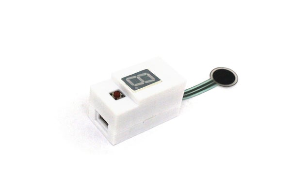
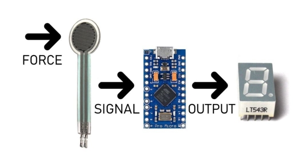
For this a Force Sensitive Resistor(FSR) and an Arduino Pro Micro is used to measure the pinching force and displayed using a 7-segment display. The FSR changes its resistance to the amount of force applied to it and we can measure that using an Arduino by treating the FSR as part of a voltage divider. It is then compared against a value store in Arduino’s EEPROM and the 7-segment displays the info. The direction of rotation shows the direction to rotate the levelling knobs. Its rotation speed shows how much it is off from the required value.
Step 2: Stuff Required
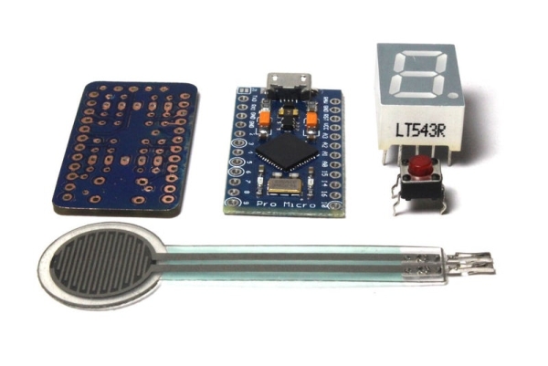
- Arduino Pro Micro
- 7 segment display
- Force Sensitive Resistor
- Custom PCB
- 3D printed case
- Push Button
- 2.2K Resistors x8
- 100K Resistor x1
- Male and Female Headers
- Blu-Tack
Step 3: Fabricating PCB: CNC Milling
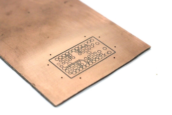
Download the Eagle file and make the PCB. It is a double sided design and does not require PTH. So it is home fabrication friendly. Iron transfer method can be used to create this PCB.
Since I have a CNC Router with me, I created this PCB using it.
Step 4: Fabricating PCB: Soldermask
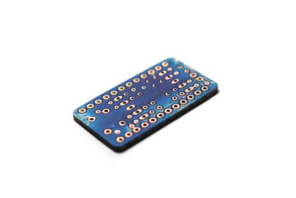
This was my first time working with soldermask for a project. Initially I drilled the holes and applied soldermask paste but then it clogs up the holes and makes soldering difficult instead of easy. So the second time around, I applied soldermask paste before drilling the holes.
Printed out the soldermask layer on transparent sheets and layered 3 per side. This was aligned and taped to the milled PCB. Then soldermask paste was applied and the transparent sheets was placed on top. This was repeated for the other side of PCB as well. Then it was cured with a UV lamp. This didn’t cure it well enough even after hours so I put them in the sun for a while and that did the trick.
After that, the transparencies were removed and the board washed with alcohol while being scrubbed slightly with a brush. This removed all the uncured soldermask paste and revealed the pads. Some parts which were supposed to have soldermask but didn’t, had a bit of the paste applied and cured. Some parts which shouldn’t have soldermask but did, were carefully scraped with a blade.
Finally the board was drilled and milled out of copper blank. The end result is a beautiful looking board.
Step 5: Solder Components
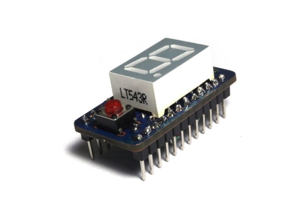
First solder all the vias. Once done, the resistors are to be soldered to the bottom side of the PCB in a vertical position as shown in image. Next solder the 7-segment display and button in place. Finally solder the male headers in place. Also cut solder female headers to size and solder to the Arduino Pro Micro.
Read more: FS-Touch Bed Levelling Tool