
Summary of Build an RFID time-clock system using Arduino
This article details the "kid-e-log," an Arduino-based RFID time-clock system designed to track arrival times for children or employees. The project uses a DS1307 real-time clock, EEPROM for data retention during power loss, and an LCD for display. It features automatic daily resets at 4 AM or via a parent's RFID tag, with no user buttons to prevent tampering.
Parts used in the kid-e-log:
- Arduino-style board (Freetronics Eleven)
- Maxim DS1307 or DS3232 real-time clock IC
- Microchip 24LC256 EEPROM
- 16 character, 2 line LCD with HD44780-compatible interface
- 125kHz RFID reader with serial output
- Four RFID tags
- Two 4.7 kilo ohm resistors
- Two 0.1 uF ceramic capacitors
- Solderless breadboard
- Nine volt DC power adaptor (300mA+)
- Enclosure
With this project you can build an RFID time-clock system to keep track of employees, children and more.
Updated 18/03/2013
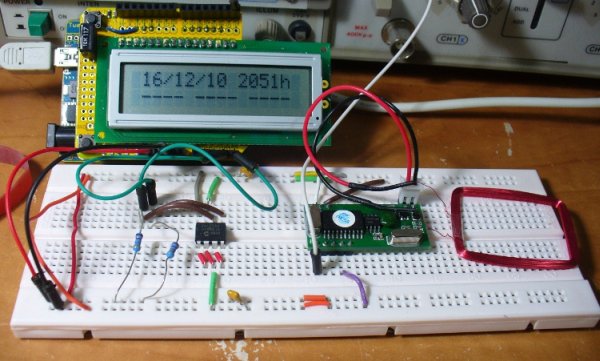
Recently I was listening to a friend who has three teenage children, of whom needed to arrive home before their parent. Unfortunately the parent needs to work all day and arrives home in the evening, and they lamented not being able to check when the children had arrived home.
After a few hours it occurred to me that a simple time clock would solve her problem – each child could check-in upon arriving home, and the parent could review the check-in times later on. And thus the kid-e-log was born.
From a hardware perspective, it would be quite simple. An LCD screen, RFID reader and some tags, and a real time clock IC such as a Maxim DS1307 – all running from the ubiquitous Arduino board. After some contemplation it occurred to me that smart kids might try to mess up the hardware by pulling the power, so it also uses an EEPROM to store time data which is impervious to power loss, and the kid-e-log will not have any user buttons. After initial programming for time and RFID key data, any changes will need to be effected by the programmer (i.e. me).
If RFID is new to you, review my Arduino tutorials before moving forward.
Before jumping ahead and making something, we discussed exactly what the function would be. Each child would have an RFID tag, and when it is read the hardware will save the arrival time in memory, and display it on the LCD. The time data will be reset automatically at 0400h or by reading an RFID card belonging to the parent. There will not be any buttons, and the hardware must be power-failure resistant – therefore EEPROM memory is needed for time data and a backup battery for the real-time clock.
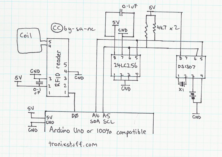
The DS1307 and the EEPROM are both using the I2C bus, and the RFID reader (more information) uses Arduino digital pin zero (serial input). The LCD is pretty straight forward as well, as described in the tutorials.
Here is the schematic for the prototype hardware:
From a software (sketch) perspective, the design is easily broken up into distinct functions which makes programming quite easy. The sketch is a basic loop, which follows as such:
- check to see if a tag is read by the RFID reader – if so, branch to the the reading function (which compares the read tag against those on file, and records the time matching the tag to the EEPROM)
- display real time, date and check-in data on the LCD – another function
- delay for a moment to stop the LCD flickering from fast updating
- check if the time is 4am, and if so call a function to reset the check-in times
From each of those four main instructions, functions are called to handle various tasks. For example the displayData() funtion is used to read the DS1307 real time clock, and display the time and date on the top line of the LCD. Then it reads the contents of the EEPROM, and displays the check in time for each RFID tag – or a line if they have not checked in yet.
From a hardware perspective, the requirements are quite simple:
- An Arduino-style board of some sort (we used the Freetronics Eleven)
- Maxim DS1307 or DS3232 real-time clock IC
- Microchip 24LC256 EEPROM
- Usual 16 character, 2 line LCD with HD44780-compatible interface
- 125kHz RFID reader with serial output, and four RFID tags (don’t get the Weigand version!)
- Two 4.7 kilo ohm resistors (for I2C bus with EEPROM)
- Two 0.1 uF ceramic capacitors (for power smoothing on the breadboard)
- a solderless breadboard for prototyping
- a nine volt DC power adaptor, rated for no less than 300 milliamps
- And for the final product, a nice enclosure. More on that later…
For more detail: Build an RFID time-clock system using Arduino
- What is the primary function of the kid-e-log?
To keep track of employees, children, and others by recording their arrival times. - How does the system handle power failure?
It uses an EEPROM to store time data which is impervious to power loss. - Does the device have user buttons?
No, there are no user buttons to prevent smart kids from messing up the hardware. - When are the check-in times reset automatically?
The time data resets automatically at 0400h. - Can the parent reset the check-in times manually?
Yes, reading an RFID card belonging to the parent will reset the time data. - Which I2C components are used in this project?
The DS1307 and the EEPROM both use the I2C bus. - How does the RFID reader connect to the Arduino?
The RFID reader uses Arduino digital pin zero for serial input. - What type of RFID reader should be avoided?
You should not get the Weigand version; you need one with serial output. - What powers the final product?
A nine volt DC power adaptor rated for no less than 300 milliamps. - Who can change the time and RFID key data after initial programming?
Only the programmer can effect changes after the initial setup.
